|
DCC conversion
Although I have some experience with wiring,
I have to say that it is not my favourite occupation. I find that the
smallest distraction when doing the job can result in connection disasters
so I also have to put my hand up to admit that the job also makes me very
grumpy indeed! Nevertheless, I have wired up a couple of aircraft cockpits (and
flown the 'plane afterwards).
I was brought up in the era of
electro-mechanics. You could actually see what was happening in those days
and it made sense. Electronics are wonderful but my general understanding
is about that of ancient tribes observing an eclipse. Circuit boards look
to me like a mad mixture of tiny Liquorice Allsorts and Dolly Mixtures and the
sight of folks making up boards to their own design fills me with admiration.
In the old days, I had used a thing called 'pulse power'. All the locos
ran really well at scale speeds and I felt all was right in the world.
Coming back to the hobby, I found 'pulse power' was a thing of the past
and 'all it used to do was burn out motors' (funny that, because it never
happened to me). County Gate was therefore controlled using
DC with a Gaugemaster controller. This was not anything like pulse
power and the speeds of some of my locos were close to a Boeing 747 at
rotation.
By chance I met Malcolm Alberry at the Warley show. He was helping
out at the Digitrax stand and very kindly spent a great deal of time
explaining the systems to me in a way that even George Bush could
understand!
As a result, we opted for
the Digitrax system and begun a phased approach to digitalisation. We
purchased the Digitrax Zephyr, a transformer and some remote operating
stations. The Digitrax Zephyr manual can be downloaded
here.
Our
expectations of DCC were as follows:
-
Constant higher voltage
applied to the track. This has got to solve some of the poor conductivity
problems of DC when very slow running is required.
-
Simplified wiring as it
is not necessary to isolate track to prevent the wrong locos from
running.
-
Realistic stopping and
starting.
-
Loco performance
programmed into the chip to control top speed.
-
'cruise control' so that
the required speed is held 'up hill and down dale' whatever the load.
-
Equalisation of
performance of our L&B locos to ensure easy double heading.
-
Easier automatic
operation of the layout for exhibition purposes.
the
reality, after living with these systems is this:
-
I do not think there is
much difference in track conductivity between DCC and DC in practice
-
The wiring for a basic
system is indeed simple.
-
The locos are indeed
easier to control
-
Basic programming of a
loco is simple but it gets very difficult if you want the best
-
'cruise control'
(back EMF) might work if you make a life's work out of it but so far no
luck for me
-
It is possible to
equalise loco performance
-
Automation works very
well but the system is very complicated and expensive
I had wished to replace
the Peco solenoid motors at County Gate Station for some time and the
changeover seemed like an ideal opportunity to get that done and also to
upgrade our signals. We first of all stripped County Gate of its
wiring and Peco point motors. Feed to the track was by self adhesive
copper tape, and drop wires were put in place every metre. The amount of
wires underneath were reduced by at least 75%. I was also unhappy with
the signals at County Gate and decided to replace some of them with more
typical SR models and at the same time seek better movement and the
'bounce' found on the prototype when they are operated.
I also had got really fed
up with the permanent magnets fitted into the track to disconnect the
Greenwich couplings during shunting operations. This had resulted in a
number of involuntary disconnections at embarrassing moments. The magnets were dug out of the
track and eventually I found electromagnets strong enough to replace them.
I decided to retain the
manual operation of points and signals at this time. As such, the wiring
is indeed very simple.
The only things I have had
chipped previously are my cats. Perhaps the digital control will keep
them in order too!
Click here to check it out
Locomotives running on DC are about as clever
as a bag of hammers. When chipped, locos are far more intelligent than
George Bush! The new
chips are really very small and we were advised to choose the latest
Digitrax offering. The new Digitrax DZ 125 chip is similar in
size to the Lenz silver mini. This chip,
despite the instructions that come with it, is enabled for back EMF (BEMF)
(called 'scalable speed stabilisation' by the Yanks).
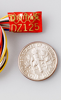
DZ 125
This offers better slow speed running and
also compensates for grades (a bit like cruise control).
At long last, the chips arrived and the exacting job of fitting them to our locomotives began. It was
necessary to virtually rebuild some of the older engines, and installation
into the L&B units was far from easy. Great care is needed to ensure that
there are no shorts in the system.
Chips can actually control other functions
too such as directional lighting. We have installed this on a few units
and it works very well indeed. The large amount of wiring needed to do
this raises challenges when working with such tiny rolling stock. I do
intend to fit sound to one unit, just for the hell of it!
The generic manual for these Digitrax chips
can be found
here
and the specific manual for the DZ125,
here
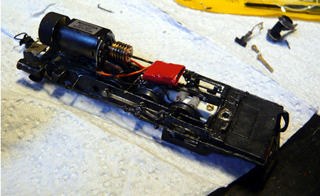
chip fitted to the
chassis of 'Taw' - click on image to enlarge
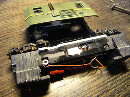
The motor unit of
the railcar converted. The part of the chassis which contacted the brushes had to be milled
away and the wires then attached to the brushes - click on image to enlarge
Once the Digitrax Zephyr outfit was
delivered, it was installed into the viaduct section of the model. The
main control box was fitted into a recess cut into the front of the
baseboard. This box is held in place with Velcro. In order to programme
locos, it is necessary to have a programming track...two leads come from
the control box to do this. We felt that this was another complication, so
the harbour branch of the viaduct section is fed through a double pole, double throw
switch to provide either track power or programming.
The leads to the UP5 remote sockets daisy
chain from the main controller. It is transferred from one panel to the
next using 8 pin DIN plugs/sockets. These also carry the track power.
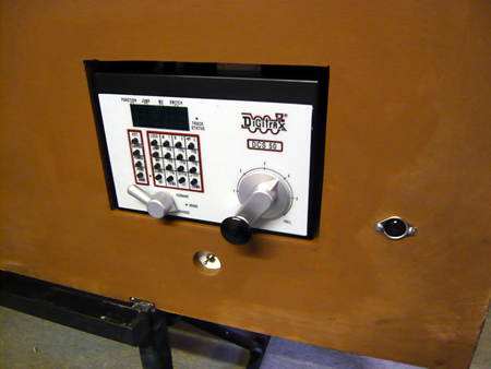
the main control box
fitted. Below is the switch to track for programming or power. The DIN
socket will feed to the harbour section
The box was 'lit up' and I have to say we
quite quickly got the hang of it. All the locos now had their numbers and
can be programmed to perform as required up to a point.
DCC promises to offer all
the characteristics that I required and there is no doubt you can programme each engine to do most things.
The programming of a loco
depends on altering a vast number of parameters. These are called CVs and
there are well over one hundred of them. These all have to fiddled with on
a programming track while your supper goes cold. In my opinion, a lot more
has to be devised to make the system user friendly.
DCC manuals seem to have been written by electronic nerds for
electronic nerds (or USA speak). I have to say that Lenz scores slightly
better in this respect, but Digitrax and NCE just make my eyes roll. Some
of the information is actually wrong and there is no logic (understandable
to British and French) to the way the manual is compiled.
There are a number of
forums available where help is at hand and this does ease the situation.
Thanks to some good
friends who are in to all of this we hope to be able to publish here the
generalised programming necessary to get narrow gauge locos to run as they
should.
Bitter experience has
shown us that it is a very bad idea to use Peco point motors or others
requiring a CDU. In 20/20 hindsight, I would have fitted Tortoise
throughout.
I find that operating trains for two whole
days during exhibitions, mind numbingly boring and subject to human error
which quite often results in derailments and wrecks! Our little engines
are very delicate and such treatment was not doing them any good. Our
Desperados have been amazing doing as well as they have and have manually
operated CG far better than I could in a million years but it has been
very hard for them at best.
'mind numbingly boring'
Far better to be able
to talk without distraction to the visitors and even have the time to
visit other stands and spend time talking to old friends. I also quite liked the idea
of just watching trains go by. I therefore decided that the layout would be fitted with
automatic train control so only the port branch coal trains and shunting would be operated by hand.
After further discussions with Malcolm
Alberry, it was decided to go the whole hog. This was a very scary
decision as the equipment is not cheap and I would not have had a chance
of succeeding without Malcolm's help. It must be pointed out that
automatic running is useless unless you have reliable operation. This has
taken a great deal of time but I can now say that we have as close to 100%
train reliability as is possible.
This has been achieved by picking up
current from as many wheels as possible. Our six coupled engines are
therefore plugged in to 'companion cars' which also pick up current. Many
modifications have also been made to the mechanisms which must travel long
distances without complaint.
I still wished to retain the potential for
manual operation of the layout without depending on electronics. This
means that we have double control panels and it is possible to change from
one system to the other by merely swapping a few plugs.
I shall try to describe how it all works
without the use of too many nerdy terms! Apologies to those who know all
of this stuff!
Apart from just controlling trains, the DCC
system also includes Loconet. Loconet is a system that allows all sorts of
electronics to be daisy chained together with a six wire cable using phone
socket / plugs. Once connected, the various electronic boards are able to 'talk' to
each other. Remember, on a DCC layout, the track remains live with a
pecial DCC voltage waveform the
whole time. Digital signals are passed down the rails to the locos which
control their operation after they are 'read' by the chip. This is how
loco lights can be switched on and off, and speed and direction control is
effected. Digital signals are also passed down through the Loconet system
and provided the right bits of electronics are provided, the digital
stream can control point, signal and block operations as well as provide
for further train control stations.
Using such systems, the DCC control board is
just fitted with push buttons. The direction of point throws and signal
positions are shown by LEDs.
Sections can be cut into one rail (must be
the same side throughout the layout) and the system can sense where trains
are, which are also shown by LEDs. It is not that dissimilar to full scale
track circuiting. The image below shows how such units fit together
on County Gate.
click on image to enlarge
Parts are Digitrax, supplied by
Sunningwell Command
Control and
CML Electronics
hover over each board for explanation - do
not click All these boards are
multi-functional and some require programming which is rather difficult.
This facility allows us to
control the entire functions of the layout through just one cable (similar
to a telephone cable). The amount of wiring is thus considerably reduced.
Once this is done, by using an interface unit, the
Locobuffer, the
whole network can be connected to a computer, using USB leads. Really complex sequencing of train operation can
then take place. The
whole concept is in effect similar to sequencing and MIDI, for those
familiar with modern musical keyboard systems. The controlling software is
supplied by Railroad &
Co. This is a very flexible system and has an excellent 'help'
forum for the sticky questions. One also has to load a Loconet programme into the
laptop.
Our first show as an
automated railway was at Chatham in June 2009 and I am pleased to be able
to say that the system worked perfectly throughout the weekend.
We do have full wiring
diagrams of County Gate. These are included for our own reference should
problems arise. However, they may give some insight into the work that has
gone into this project.
The software is well explained on
this link
Below is shown a simplified animation of how
the software operates. The route is previously set for Lyn and River Avon.
The red dot shows point motors when activated. After
the railcar and Yeo return to base, Exe and Halliday would be dispatched.
click on image to repeat
Here is an animation of how the ten trains
operate over the main line.
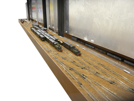
the fiddle yard with stock arranged for auto
running
example of 10 train operation - click on image to enlarge
A film of the completed
automatic operation can be
seen here

|