|
wiring DCC points
I am asked so often how to wire up DCC points
that I am now including this piece. Unlike DC wiring, the track remains
live throughout at all times. The downside is that it is only too easy to
drive a train into a point that is set against it. This can be prevented
by extending the length of the isolated sections of the frog.
This is the simplicity of DCC as you no
longer have to worry about isolating sidings in order to stop the wrong
locos working as you choose the loco you wish to operate by selecting its
address. If the layout is already wired for DC, it will almost certainly
work for DCC as well, by the way. The only problem will be that you won't
be able to run another loco on one of the isolated track sections.
So let us first look at the basic wiring
requirement.
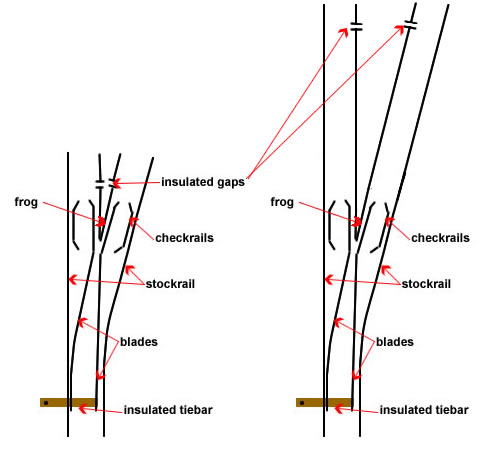
The only thing we have to do is to change the polarity of the frog
and blades when the running
direction is changed. This means that the frog must have insulated joints
to prevent a short circuit. Click on the switch below to animate.
DC
turnout
- click on switch to
operate
Despite many articles that
describe 'DCC Friendly' points, I did not bother to install them because
if you
are using Peco 'Crazy track' points it is extremely difficult to do so.
Just to explain what DCC friendly points are.
Some people are concerned that when running DCC which has a slightly
higher voltage (15VAC), a wheel might short circuit between the blade and
stock rail, so they add an additional rail break so the the blades are
always the same polarity as the adjacent stock rail. Indeed, learned
article abound on the web about 'friendly' points. Again, click on the
switch to see operation.
The new range of Peco 'Mainline' points are
excellent and can be transformed to DCC friendly in minutes. It is
therefore worth while doing so.
DCC 'friendly turnout' -
click on switch to operate
So lets look at the installation using Peco
point solenoids and polarity switch. Firstly, I solder a 'dropper' (a thin
length of wire) soldered on the underside of the frog. Once the exact
position of the point has been established, drill a hole in the baseboard
to allow the dropper to pass to the underside and drill a slot to give
adequate clearance for the actuating rod which passes through the hole in
the tiebar. The point is then fitted and fastened down (I just epoxy them
onto the baseboard). The fishplates are soldered to the adjacent rails but
do not forget to use insulating fishplates on both sides of the frog.
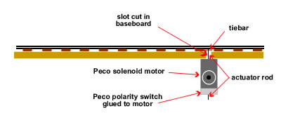
I then temporarily wire up the solenoid
including a switch and then epoxy the motor to the underside of the
baseboard. I make sure that the blade are held midway between the stock
rails and that the actuating rod is at the centre of the slot. As the glue
begins to go off, I operate the point and adjust if necessary to ensure
that there is an equal throw and that the blades go fully over.
Once the glue has gone off, I add the
polarity switch which I also glue on.
-
Make sure that the motor
is placed at the centre of the throw. If it is not, you will see the
actuating rod bounce back toward the centre. If this happens, the
polarity switch will not operate.
-
If you do have to remove
a glued solenoid motor, a couple of light taps with a chisel will release
it.
You are then ready for final wiring. The Peco
solenoid motor is operated through a Capacitor Discharge Unit (CDU). This
gives a good belt of electricity which powers the solenoid. CDUs are
powered from a 15V AC transformer. You must use a momentary contact switch
as holding power onto the solenoids will burn them out. Click on switch to
operate the image below.
The Peco turnout maintains blade position by
a small spring hidden near the tie bar. These can fail and the system will
no longer properly hold the blades in place. If this happens, you can
replace the Peco motor with a latching Seep motor which is available from
Gaugemaster. The wiring is the same.
|
Peco
solenoid point motors and route setting |
In 20:20 hindsight, I made a big error in
using Peco point motors on the fiddle yard. We use DAC 10s (CML) and DS44s
(Digitrax) to operate the point motors. There is the facility to set these
units for operating solenoid motors as they have built in CDUs, however
the signal was just not strong enough to operate the points. We therefore
had to use the signal to operate relays connected to a large CDU in the
fiddle yard.
This worked but required a four second delay
in operation between each point actuation when routes were being set by
the Railroad & Co software. This much delayed the time when trains were
not operating on the line.
In the end, we have also been forced to add
individual CDUs to every point. This has meant that three 24V AC power
units are needed to operate them but at last, the routes can be set in
'rapid fire'. Altogether a big mistake and we should have used Tortoise
motors to avoid the problem in the first place.
Hex
Frog Juicer (HFJ)
So this mad sounding piece of electronics is
duly installed. Delivered from
Digitrains, I
am happy to say that it does just what it says on the box. The polarity
switches on my Seep motors were retained to continue operating the point
position lights on our switchboard. The droppers from the frogs were
attached to the HFJ and the HFJ was wired to track power. Nothing could
have been easier.
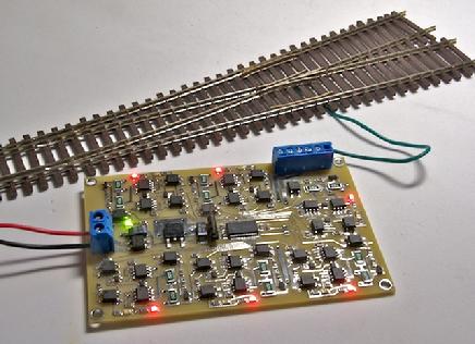
the six point unit as fitted to CG
Under test, the polarity changed instantly
and the momentary short was not registered either by the trains,
Digitrax system or the Railroad & Co software. A perfect result in fact.
The unit is not cheap but if one is looking for 100% long term
reliability, well worth the cost of £8 a point in my opinion. Single and
double units are also available. The LED light show is quite impressive:
pity it is hidden under the baseboard!
The unit also does miracles for more
complicated trackwork such as crossings and slips.

|