|
Birth of a railcar
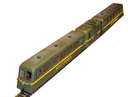
the prototype railcar delivered in 1934
It might seem a bit potty
writing about how I developed a railcar for County Gate, but the exercise
might serve to help those building freelance designs to achieve results
that may be more realistic and credible.
Thanks to the internet, we
are now blessed with an almost infinite information resource and there can
be little excuse for historical inaccuracy. I spent three times as long
developing the design as I did building it. For me, I must say, this is
the best bit.
I worked to the following
criteria:
1. Railways
were a business, so there has to be a jolly good reason for the company to
spend any money.
2. The
resulting equipment must be 'fit for purpose'.....(I have always wanted to
use that expression!)
3. The
equipment has to reflect technology of its time taking into account the
budget available.
4. The
aesthetic design should reflect the trends of the time.
Unlike less fortunate
narrow gauge lines such as the Festiniog, the Minehead and Barnstaple
enjoyed financial backing that saved it from improvisation.
operating criteria were as
follows:
1. Low
operating costs with minimum staff requirement and training.
2. Driver
control from each end.
3. Instant
deployment and let down.
4. Good
acceleration.
5.
Comfortable, silent with good views of the landscape.
6. Well lit
and heated.
7. Minimum
damage and wear to trackwork: no hammer blow and low axle ratings.
8. Reflect the
'modern image' of the Southern Railway.
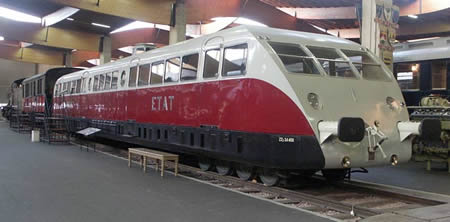
Huge advances had been
made in railcar design in France and by 1931, the Bugatti factory was
producing main line high speed railcars for their Paris to Lyon service.
One of these units is preserved at the National Railway Museum at Mulhouse.
These advances also
trickled down to the metre gauge lines throughout France with considerable
success.
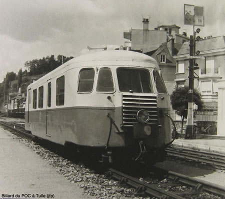
Billard Autorail on the Corsican Railway
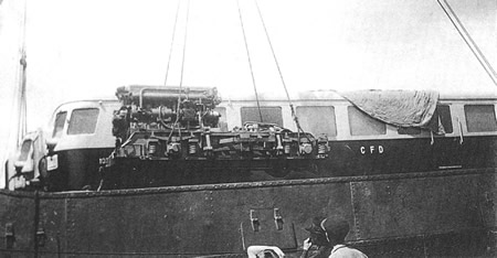
the motor bogie of a Billard
There was a surge in
'modernism' which had also begun to grip management at Eastleigh. It was
therefore decided that the new railcar would incorporate all the latest
practices and reflect the modern image. Great Britain had been somewhat
slow to embrace the diesel engine, in part due to the ongoing dislike of
anything German. The British Company, Gardner, had begun to produce an
excellent range of diesel engines in the lower power ratings but it was
not until after WW2 that the more powerful 8 cylinder engines came into
production.
Transmission was given
some serious consideration. A number of railcars had been built in
Ireland, using buses as the donor. These units had mechanical gearboxes
and were provided with only one reverse gear. This meant that the units
had to be turned at each end of the line. Such an arrangement was
unacceptable for Eastleigh, so hydraulic and electric traction were
investigated. Considerable experience had been gained with electric
traction for many years with tram systems. With power on board, lighting
and heating could also be easily arranged. In addition, diesel/electric
traction meant that the engine operated at a fixed r.p.m. which was
far easier to operate with remote driving positions and engine life would
be significantly increased.
The Swiss company of Sulzer was therefore chosen to supply the power units.
Running gear would be all
bogie, which would reduce track damage, minimise axle loadings, permit
greater speed and offer the best comfort. By placing the tractor unit at
the centre of the consist in a separate car, noise and vibration could be
minimised. A narrow corridor would be provided for passage of the guard
and bellows corridors fitted to each passenger car. The engine compartment
was separated by a soundproofed partition. A large electrically operated
fan was installed at roof height to draw air through the radiator.
click to enlarge
The bogie design was
advanced for the time, with the provision of the newly developed Armstrong
lever hydraulic dampers to control roll. Braking used the Westinghouse
system with air provided by an electric powered compressor.
These were constructed
using the Voisin semi-monocoque system that had been developed in the
1920s. Door and window pillars were cast aluminium, flush riveted to a
light steel frame panelled by aluminium panels. The assembly was mounted
on a ladder frame. The windows were laminated glass and did not open.
Ventilation was provided using a forced air system and heating and
lighting were electric. Comfortable seating was provided in art deco
style. An offset corridor gave access to seating and ingress was effected
by air operated sliding doors. The newly invented Kent Clearview
units were fitted at the drivers stations to clear rain. These consisted
of a spinning disc of glass which threw out rain droplets. The drivers
stations were provided with remote engine instruments, brake and pressure
gauge and a 'dead man's throttle'. A master key was utilised to immobilise
the unused station. The engine could be started from either end.
Loading gauge restrictions
maintained the overall dimensions similar to the existing coaches on the
line.
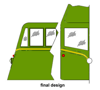
The design would be flush
riveted throughout. The nose section was worked on several times before
the final design emerged.
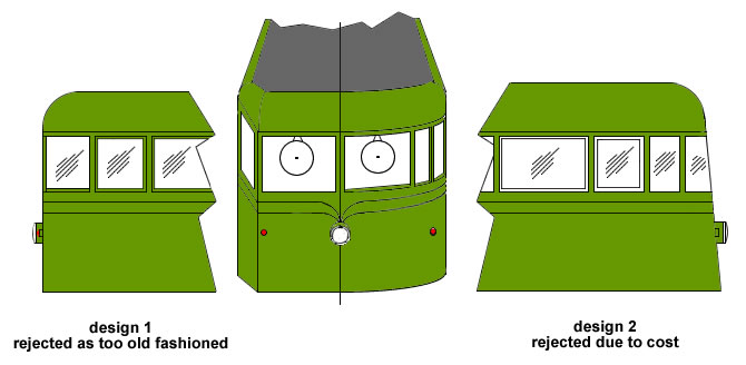
During the 1930s,
aerodynamics had become better understood by the public. If the railcar
was to be successful, it would have to significantly reduce journey time
compared to buses and private cars. (This concept is correct. The metre
gauge line Nice/Digne is still operating to this day for local traffic due
to the bad roads.)
The final design was much
further raked which was felt would depict speed best on advertising
posters. The front however was flat to reduce construction costs and the
window height raised to improve views of the countryside..
The railcar was completed
in three long days over a wet holiday weekend. A Graham Farish long
wheelbase bo-bo chassis was purchased new from Hereford Model Shop. This
effectively set the length of the tractor unit.
The plastic outside bogie
frames were removed and the coupling boxes sawed off. The sides were then
painted and weathered prior to refitting. The foundations of this
articulated railcar are the corridor bellow connections. These will be
later epoxy glued to the chassis, (BUT NOT YET). They should be a tight
fit onto the chassis body and should be made really square as the
passenger cars will be supported on them. Thin square section Plasti-strut
is glued to the outside to represent the bellows. Once dry, the grooves
were 'distressed' with a cut-off disc using a Dremel. Once the part looks
like a corridor connection, it is quickly coated with Plastic-weld to melt
off any fur. The bellows were then painted and weathered and left to dry.
It is now time to make the
car sides. Unless you wish to get into resin casting, they will be made in
1mm Plasticard. I always lightly sand one surface to remove the gloss. It
makes marking out much easier. The window apertures are carefully marked
and the corners drilled with a .5mm drill. This makes removal of the
blanks far easier. Remember that accuracy here will make or break the
resulting model. The blanks are then carefully scribed with a very sharp
craft knife and then 'popped' out. Great care is needed not to distort the
narrow window pillars during this process. The apertures are then cleaned
out very carefully with the knife, making sure that the cuts are square.
The window and door apertures are then filed into a rounded profile.
You will need to prepare 4
passenger car sides, (2 mirror images), 2 ends and the sides of the
tractor car.
I do not intend to present
scale drawings for this model. The exact design and sizes are up to you!
Once the work is done, it
is time to make the curved roofs. Select 3mm square Plasti-strut (or
laminate thinner sections together) and glue flush to the tops of the car
sides and to the sides of the front panels. The unit can then be
assembled.
Next to make and install
are the floors. These are in 1.5mm Plasticard and are recessed into the
body to accommodate the bogies. We purchased two good quality N gauge
coach bogies. These are mounted on Plasticard bolsters glued to the floor.
On our model, clearance below the coach side was set at 3mm. Remember that
the floor does not extend right to the back as the drive bogie has to be
accommodated. Once the complete assembly has thoroughly hardened up, the
really boring bit starts.....sanding the curves of the roof. For removing
most of the material, I used 100 grit production paper glued to a really
flat surface. Take great car as it is much harder to put material back! I
finished off with 180 freecut paper. Any slight gaps in mitring can be
filled with car bodyfiller.
Now is the time to cut and
fit the inner window frames. These are 0.5mm smaller than the apertures.
Despite best effort, there will almost certainly be some variation in
window size. Just offer up a thin piece to Plasticard and mark around the
hole with a 0.5mm Rapidograph. Remember to pre-sand the surface so that
the ink takes. The inner frames are then carefully glued in. The rear
sliding door should be made of 1mm plastic.
It is then time to add
detail. Bogie inspection hatches can be scribed in and hinges made in very
thin Plasti-strut.
A hole is then drilled
dead central at the rear of the support plate to take a small screw. This
will act as the articulation pivot. The nut of the screw is fitted into a
corridor bellows. I fitted the nut 5mm in, so that even when the cars were
around a sharp corner, the end of the bellows cannot be seen. Firstly
drill through the bellows with a clearance hole for the screw. Then attach
nut to screw and whilst heating with a soldering iron, slowly push the nut
into the bellows so that it is flush. Make sure that the screw remains
upright.
Screw coach units to
bellows.
The build is very similar
to the coach units except that no floor is fitted. It will be attached to
the bellows once these are glued onto the Farish chassis.
Once the square section
plastic has been glued to the roof, fill with car body filler and sand
flush. Sand the curves into the plastic extrusion as before. Drill two
clearance holes 3 mm from each end of the car dead central. Then drill to
partial depth a larger hole to lose the head of the screw.
|
fitting the corridor
connection |
Place the motor chassis on
a sheet of glass and slide on the bellows at each end with the passenger
cars attached. Drop on the tractor car body and ensure that there is
sufficient clearance between the units to allow for the track curvature
required. Apply 5 minute epoxy to the inside of the bellows and attach to
the Farish chassis. The height of the bellows can be adjusted at this time
to ensure that the passenger cars are absolutely level. Once satisfied and
the glue has hardened, offer up the tractor body and pilot drill through
to the bellows. Again, nuts can then be melted into the plastic of the
bellows.
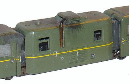
the tractor unit of the prototype
This is up to you. We
fitted lights made out of plastic tube. This were filled with epoxy to
near the surface and reflectors painted on. Once dry, a drop of epoxy
hardened to become very convincing lenses. We made louvres from Plasticard
and installed the exhaust system. We also added fuel filler and water cap.
We also added a strip along the length of the units as a waist.
Once satisfied, dismantle
the model and spray the required colour. We use a plastic etch paint
first, supplied by Currys. The interior of the passenger cars is then hand
painted to the required colour. Transparent plastic is then fitted to the
windows. We use 'Clearfix' for this. Add seats and passengers and then
attach the roof, cut from thin plastic sheet. Mask off the model, and
spray the roof.
We ballasted the passenger
cars with lead shot glued to the underside. Add door handles, couplers if
you wish but buffers for a minimum, etc...and I guess you are about there.
Enjoy breaking new ground in railcar design and don't forget, that many
young people can relate to such machines much easier than steam engines.
The model runs better than
anything else we have on the line and the articulation looks wonderful
round the curves. We built ours for a minimum radius of 12".
At the end of 2010, this
railcar was withdrawn from service as there are sufficient trains now to
use all the available slots including spares.

|