|
Building the Kitson Meyer
The Meyer design was reworked by Kitson who moved the
bogies apart sufficiently to allow for a conventional firebox and grate
to fit between them. As such, they were one of the most successful
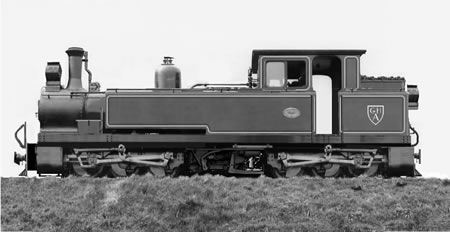
articulated designs in the world. A freelance Kitson Meyer was developed
using many of the features of the Leek and Manifold tank engines, that I
so much admire.
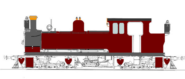 the design is getting
close to looking right. There is a great deal of the Leek and Manifold
tank in the design!
the design is getting
close to looking right. There is a great deal of the Leek and Manifold
tank in the design!
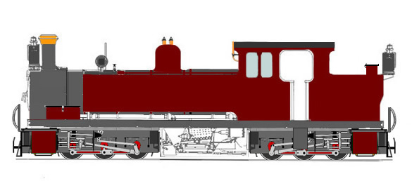 this is the same design
with Grafar 08 chassis
this is the same design
with Grafar 08 chassis
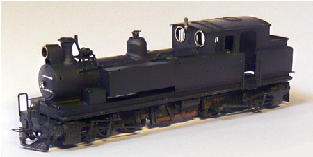
 this is a photo mock-up
of the engine
this is a photo mock-up
of the engine
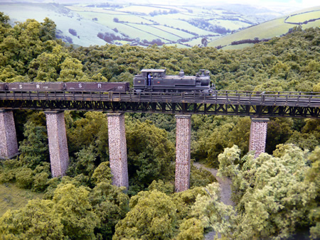
This build is one of my typical freelance
jobs. Mostly I worked from the photo mock-up that I made and very few
measurements were actually taken. In a way, like the Mallets, it has
been more of a loco sculpture than anything else but for me, I find it
easier to get the proportions looking right this way.
The loco was built with the most basic of
equipment: a Dremel, 25 watt soldering iron and some hand tools and of
course the wife's best kitchen scissors.
The fixed dimensions were the Bachmann
class 08 bogies, the side windows and spectacle plates left over from
Backwoods Manning Wardle kits and the rest more or less fell into place
on its own.
The first job was to graft the Roco valve
gear and cylinders onto the Bachmann class 08 chassis. The rear part of
each chassis was removed. Normally, the Roco valve gear stands higher
than the platform of the 08 chassis.
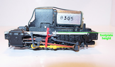 The 'comfortable' position for the valve
gear
The 'comfortable' position for the valve
gear
In this case, it could not be allowed
otherwise the loco would look like it was on stilts. Some butchery was
needed including the shortening of the expansion links so that the whole
lot did not protrude higher that the chassis footplate. In the end, with
a lot of fiddling, it all worked freely.
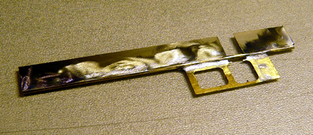
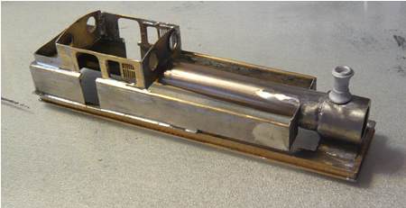
The main frame
which supports the boiler and cab was then soldered up. This was an
'I'
section purchased from
Eileen's Emporium. I always work on a sheet of glass in order to make
sure everything goes together perfectly flat.
click on image to
enlarge
Due to the variations and evolutions of the
L&B Manning Wardles, quite a few etchings are never used. I selected the
cab etching for the locos as originally built and cut the window
sections out. These were butt soldered to nickel silver off cuts
from coach kits and the whole cut to the correct shape. The main feature
of this loco are the curved tank tops and waisted cab. This was achieved
by soldering a thick brass wire to the cab and then soldering the tanks
on the opposite side of the rod. This done of a sheet of glass results
in a perfect job.
For the time being, I left the rod crossing
the cab entrance in order to keep the whole thing in shape.
 the finished result
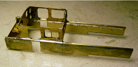
The window frames were added followed by
the spectacle plates (brass surrounds soldered in first) and the whole
assembly soldered up. Take care to ensure that it it all squared up.
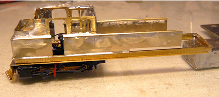 the assembly is then
soldered to the frame
-
click on image to enlarge
the assembly is then
soldered to the frame
-
click on image to enlarge
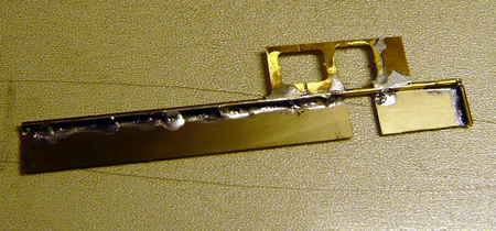
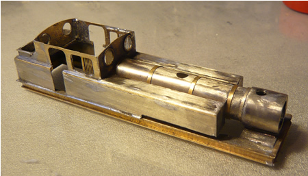
The smoke box and boiler top was made
simply by heating the metal sheet and wrapping it around a former.
 smokebox and boiler
rolled and fitted - click on image to enlarge
smokebox and boiler
rolled and fitted - click on image to enlarge
 the tank tops are then
added
the tank tops are then
added
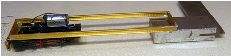
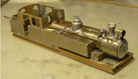 generator fitted along
with tool boxes - click on image to enlarge
generator fitted along
with tool boxes - click on image to enlarge
 click on image to
enlarge
click on image to
enlarge
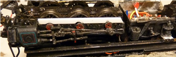
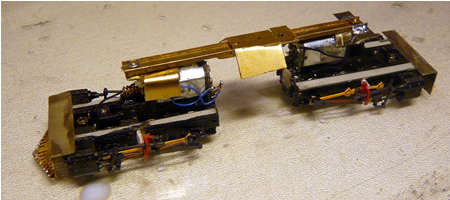
The two bogies have to be insulated from
one another as they will be of opposite polarity. The brass saddles
which fit over the motors, (with the pivot over the centre driver) are
coated with epoxy and when dry, the saddles are epoxied onto the motors,
ensuring that the rubbing plates are perfectly flat. The front bogie
(left) is left more free moving by placing a thin washer between the
rubbing plates. The rear, however. is stabilised much more with wide
running plates to prevent the loco rolling.
 click on image to
enlarge
click on image to
enlarge
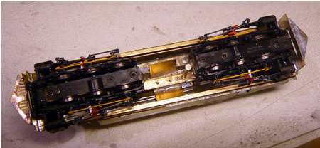
The chassis is fitted into the body using
two locating pins and an extended screw to make assembly easy. The
firebox will be built up from the visible 'wings'.
 click on image to
enlarge
click on image to
enlarge
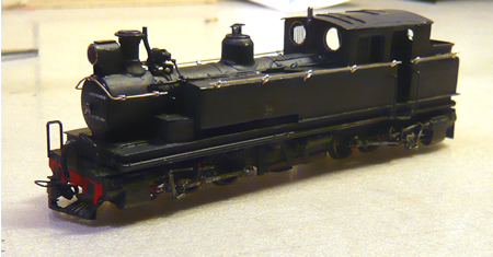
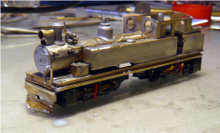
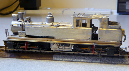
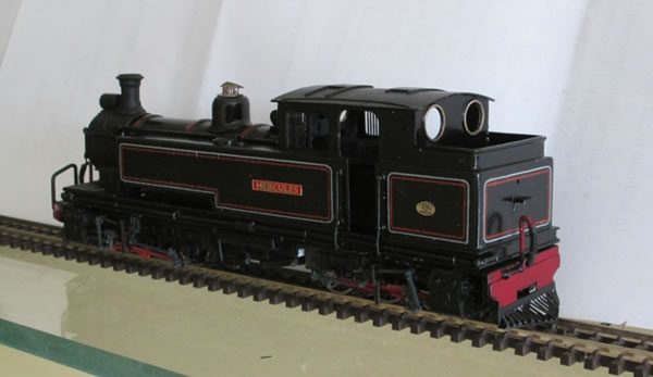
This is the loco which is now ready for
painting. The handrails will be fitted later. One of the tough jobs was
the drilling of handrail knob holes through the thick brass rod that
forms the tank top curve. The result was much larger holes than I
wished. This was cured by refilling the holes with solder and then
drilling the right size.
 click on image to
enlarge
click on image to
enlarge
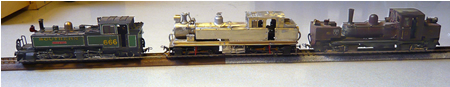
This is the size comparison with our
Mallets and Garratt.
I have experienced several loose wheels. This
is what I suggest:
On initial stripdown, degrease axles and wheels and run into the wheel
boss, a small quantity of Locktight 603 and leave overnight. This should
prevent these stupidities.
Several phosphor bronze are often on in contact with the wheels....check
for this..
Positioning of the Roco cylinders. Remove
motor. Use 5 minute epoxy to attach and have the return crank already
fitted into the rear crank. There is then a short window of opportunity to
ensure that there is free movement of the gear.
Once the cylinders are fastened, push the chassis along to check for any
binding between the coupling rod and the slide bar support bracket. Only
then replace the motor but glue this in position as well, as the extra
weight of the valve gear can cause the motor to 'jump' and strip the
gears.
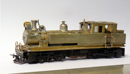
After looking at the loco for a few hours,
I have changed a few things. The safety valves (which came from a
Langley 'Lyn' dome) looked crude so they were replaced with a scratch
built version. As indeed was done with a number of these locos which
suffered from loading gauge issues, the footplate floor has been 'underslung'
to the bottom of the support frame and the hand rails extended down
lower than originally planned. Finally, the front vacuum pipe has been
transferred to the bogie and rails placed on the pilot in a similar
manner to many Mallets. Several Kitson Meyers carried them and it must
have been far easier to work in the smokebox.
Finally, I have turned a proper whistle
using brass rod in my Dremel.
click on image to enlarge
After the fitting of the sandboxes, made of
thick Plasticard, The body was placed in the ultrasonic cleaner with a
tiny touch of soda to neutralise the flux, followed by a clean rinse.
Once dry, the body was sprayed with etch primer.
At this point we had some chip issues but
thanks to Andy of DCC Supplies, the problem was quickly resolved. The
handrails have been temporarily fitted and very shortly, it will be off
for finishing and lining.
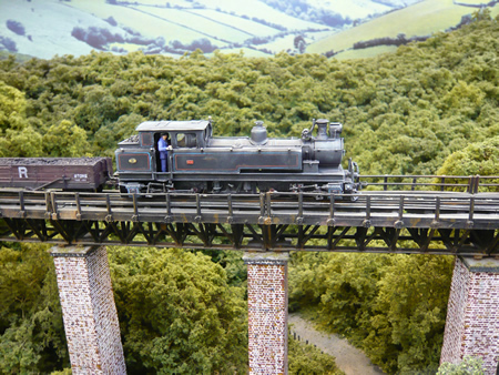
The loco has been lined and weathered in a
first class fashion by
Robert
Kaczmarczyk who is available for custom projects. It has now joined
the fleet and I must say, runs most smoothly despite a slight 'waddle'.
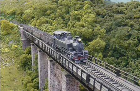
This locomotive has covered quite a mileage
and has waddled all the way. I suspected an out of round wheelset but
this was not the case. It would appear that the high pivot point needed
to create the Kitson Meyer configuration causes the valve gear loading
to be magnified. Another modeller has made an excellent similar model
and it also waddles! Case is proven.
 The lovely model built
by Phil Mortimer in the USA.
The lovely model built
by Phil Mortimer in the USA.
The problem has been solved by stabilizing
the wheels using plastic strip attached to the outside frame with epoxy
glue. The moulded hornblocks are first trimmed off. This has much
mitigated the problem.

|