|
Building 'River Avill' No 797
see movie of this loco in action
Well known modeller, Bernard Taylor came up
with a drawing of an Armstrong Whitworth narrow gauge diesel electric
locomotive of the early 1930s. He then went ahead and has just produced
some first class etches of the model. It is designed to fit on the
Bachmann Class 08 chassis.
click on image to enlarge
If Eastleigh had wished to experiment with
this concept, as well as its new railcar programme, a single unit would
have been inadequate. They would have expected at least as much traction
as produced by their Mallet design. I have therefore redrawn the loco as
a double articulated unit.
click on image to enlarge
Bernard very kindly drew out a different
front which in my mind was more appropriate to fit in with the Eastleigh
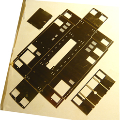
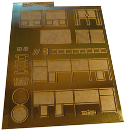
design concepts. We received the first set of etchings, and very nice
they are too.
 click on images to enlarge
 click on image to enlarge
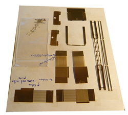
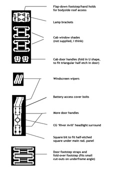 small part identification -
click on image to enlarge
small part identification -
click on image to enlarge
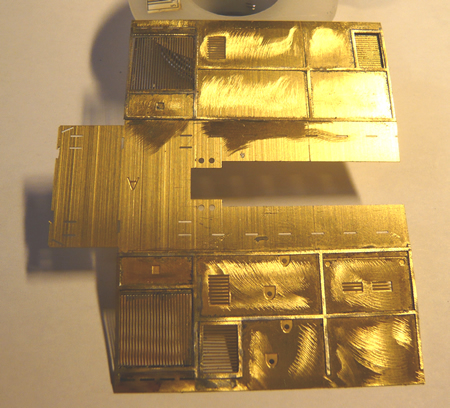
The test etch from Bernard , I must admit
contains many lovely bits which frankly I cannot figure out where they
go! I am sure that this will be resolved once this kit goes on sale.
Seeing as my own model is going to be quite different, I have ploughed
my own furrow. After cutting the fret to remove one panel, the first job
was to sweat on the panelling. Great care is needed to prevent solder
spreading around. The grills were soldered at the rear.
 click on image to enlarge
 click on image to enlarge
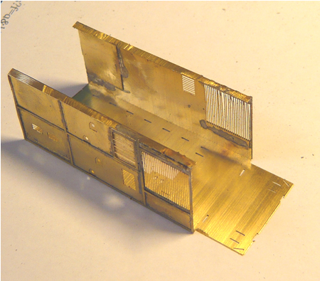
The fret was then folded using a bending
tool. Bernard was kind enough to include a different front which I felt
was more in keeping with the County Gate style. This was also folded as
was the outer panelling. The front was then soldered to the assembly.
 click on image to enlarge
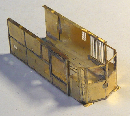
The buffer beam and lower valance were then
attached. To cross members were soldered at roof height with captive
nuts to attach the roof.
 click on image to enlarge
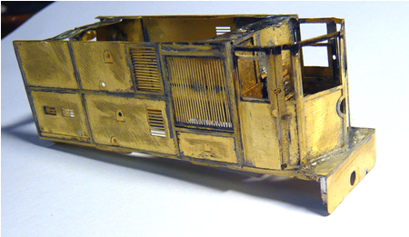
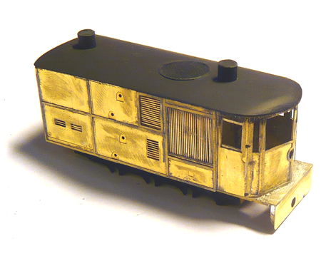
The roof is made from flat brass sheet. The
profile of the roof is built up from car body filler. Below, the body is
on the outside frames of a class 08 chassis.
 click on image to enlarge
 as far as we can go for now - click on image to enlarge
The second fret arrived and shortly
afterwards, two Bachmann chassis and a cow catcher set from Langley. The
next body went together nicely. As the two chassis are to be operated
back to back, the wiring of one needs to be reversed. The coupling box
at the front of each chassis was removed and a small hole drilled
through the chassis to take a fine brass wire that will become the pony
truck pivot pin.
The pony truck was fabricated from the four
wheel bogies supplied. Axle boxes were made out of small bore brass tube
filled with solder. A fine hole was drilled in these to take the needle
point wheel sets.
I have experienced several loose wheels. This
is what I suggest:
On initial stripdown, degrease axles and wheels and run into the wheel
boss, a small quantity of Locktight 603 and leave overnight. This should
prevent these stupidities.
Several phosphor bronze are often on in contact with the wheels....check
for this..
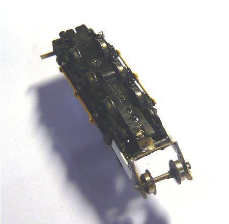
Positioning of the Roco cylinders. Remove
motor. Use 5 minute epoxy to attach and have the return crank already
fitted into the rear crank. There is then a short window of opportunity to
ensure that there is free movement of the gear.
Once the cylinders are fastened, push the chassis along to check for any
binding between the coupling rod and the slide bar support bracket. Only
then replace the motor but glue this in position as well, as the extra
weight of the valve gear can cause the motor to 'jump' and strip the
gears.
Chassis with pony truck fitted. The chassis is extended with plastic
strip.
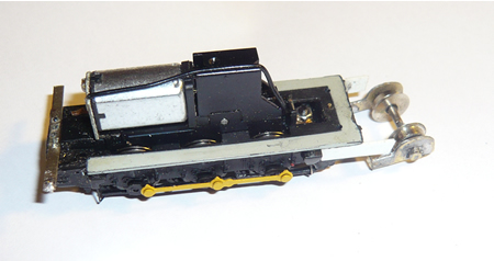
 the underside of the chassis. One wheel
has been grounded to the axle. The pony truck is yet to be weighted.
the underside of the chassis. One wheel
has been grounded to the axle. The pony truck is yet to be weighted.
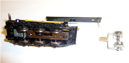 The modified keeper plate showing
pony truck retainer pin. The height of the pony truck pivot will be
maintained with a spacer.
- click on image to enlarge
The modified keeper plate showing
pony truck retainer pin. The height of the pony truck pivot will be
maintained with a spacer.
- click on image to enlarge
 The start of building the steel corridor connection. To prevent short
circuiting between the two opposite polarity bodies, much of the
corridor connection had to be replaced by plastic. - click on image to
enlarge
The start of building the steel corridor connection. To prevent short
circuiting between the two opposite polarity bodies, much of the
corridor connection had to be replaced by plastic. - click on image to
enlarge
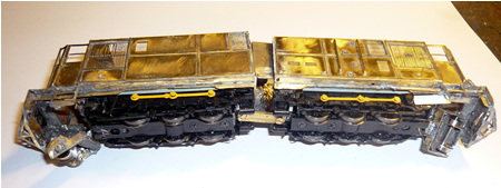 The pony trucks are now weighted with lead and the chassis link added. I
realised afterwards that the two chassis are of opposite polarity, so
the drawbar had to be divided with a plastic centre section -
click on image to enlarge
The pony trucks are now weighted with lead and the chassis link added. I
realised afterwards that the two chassis are of opposite polarity, so
the drawbar had to be divided with a plastic centre section -
click on image to enlarge
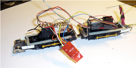 The chassis are wired up to a DZ 143 Digitrax chip. The extra
wiring is for the directional lighting- click on image to enlarge
The chassis are wired up to a DZ 143 Digitrax chip. The extra
wiring is for the directional lighting- click on image to enlarge
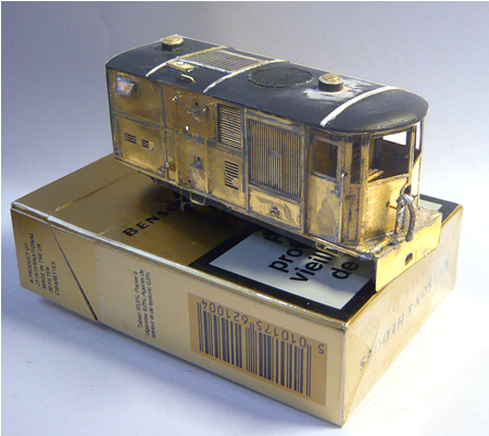
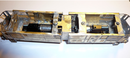
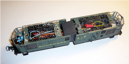 The bodies have been painted and detailed and the interior cavity
filled with lead shot wherever possible!- click on image to enlarge
The bodies have been painted and detailed and the interior cavity
filled with lead shot wherever possible!- click on image to enlarge
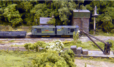
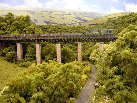
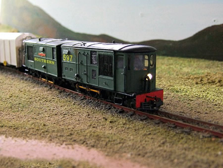 the completed 'River Avill' on Simon Coward's Isle of Mudd layout- click on image to enlarge
photo by Mick Thornton

|