DCC points & sections   programming track


  multi D pin key   viaduct DCC panel
  key to DIN plugs    viaduct DCC panel reverse
  viaduct drop down board    viaduct panel wiring table

  viaduct board wiring    

DTM30 POINT CELLS

The DTM30 has 30 cells, each of which can be used for either point control or detection indication. To control a point, we will use one cell.  In this example - CELL1.

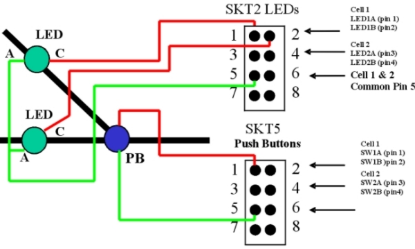
To control and indicate the current direction of the point with LEDs, a DTM30 will use two groups of output from cell1,

            -           one from SKT2 - LED drivers     - LED1A and LED1B

            -           one from SKT5 - Push Button     - SW1A

The DTM30 would be programmed to use CELL1 as a Point Cell 

Note:  On LEDs - C=Cathode, A=Anode:  Anodes are common = green line

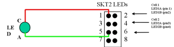
To detect the position of a loco, we would use a detection circuit – called sensor in DTM language. Here we will use CELL 1 only for driving one LED (LED1A) to show that a loco has arrived at that sensor location. The DTM30 would be programmed to use CELL1 as a Sensor Cell. The next sensor would be connected to Cell 2 in the same way from different SKT2  pins.


Viaduct DTM30 Wiring to Control Panel

     
        Point Push Buttons SKT 5             LEDs SKT 2      
                        Anode usually has a longer lead than the Cathode  
Cell #  Point # SKT # Pin # Point PB # Point # PB SW #  Cell  DCC   Cell #  Block # SKT # Pin # LED # LED #  LED #  Cell  DCC
        Pin 1 COM Pin 2   Setting Address           Cathode  Anode   Setting Address
1 1 5 1 1   SW1A Point     1   2 1 P1S   LED1A    
    5 2     SW1B           2 2 P1T   LED1B    
2 2 5 3 2   SW2A Point     2   2 3 P2S   LED2A    
    5 4     SW2B           2 4 P2T   LED2B    
    5 5   P1/2 COM             2 5   P1/2 COM      
3 3 5 6 3   SW3A Point     3   2 6 P3S   LED3A    
    5 7     SW3B           2 7 P3T   LED3B    
4 4 5 8 4   SW4A Point     4   2 8 P4S   LED4A    
    5 9     SW4B           2 9 P4T   LED4B    
    5 10   P3/4 COM             2 10   P3/4 COM      
5 5 5 11 5   SW5A Point     5   2 11 P5S   LED5A    
    5 12     SW5B           2 12 P5T   LED5B    
6 6 5 13 6   SW6A Point     6   2 13 P6S   LED6A    
    5 14     SW6B           2 14 P6T   LED6B    
    5 15   P5/6 COM             2 15   P5/6 COM      
7 7 5 16 7   SW7A Point     7   2 16 P7S   LED7A    
    5 17     SW7B           2 17 P7T   LED7B    
8 8 5 18 8   SW8A Point     8   2 18 P8S   LED8A    
    5 19     SW8B           2 19 P8T   LED8B    
    5 20   P7/8 COM             2 20   P7/8 COM      
9 9 5 21 9   SW9A Point     9   2 21 P9S   LED9A    
    5 22     SW9B           2 22 P9T   LED9B    
10 10 5 23 10   SW10A Point     10   2 23 P10S   LED10A    
    5 24     SW10B           2 24 P10T   LED10B    
    5 25   P9/10 COM             2 25   P9/10 COM      
    5 26 N/C               2 26 N/C        


Viaduct DTM30 Wiring to Control Panel

     
        Point Push Buttons SKT 6             LEDs SKT 3      
                        Anode usually has a longer lead than the Cathode  
Cell #  Point # SKT # Pin # Point # Point # PB SW #  Cell  DCC   Cell #  Block # SKT # Pin # LED # LED #  LED #  Cell  DCC
        Pin 1 COM Pin 2   Setting Address           Cathode Anode   Setting Address
11 11 6 1 11   SW11A Point     11   3 1 P11S   LED11A    
    6 2     SW11B           3 2 P11T   LED11B    
12 12 6 3 12   SW12A Point     12   3 3 P12S   LED12A    
    6 4     SW12B           3 4 P12T   LED12B    
    6 5   P11/12 COM             3 5   P11/12 COM      
13 13 6 6 13   SW13A Point     13   3 6 P13S   LED13A    
    6 7     SW13B           3 7 P13T   LED13B    
14 14 6 8 14   SW14A Point     14   3 8 P14S   LED14A    
    6 9     SW14B           3 9 P14T   LED14B    
    6 10   P13/14 COM             3 10   P13/14 COM      
15 6T 6 11 6T   SW15A Point     15   3 11 6T   LED15A    
    6 12     SW15B           3 12     LED15B    
16 4T 6 13 4T   SW16A Point     16   3 13 4T   LED16A    
    6 14     SW16B           3 14     LED16B    
    6 15   6T/4T COM             3 15   6T/4T COM      
17 SHT 6 16 SHT   SW17A Point     17   3 16 SHT   LED17A    
    6 17     SW17B           3 17     LED17B    
18 ESS 6 18 ESS   SW18A Point     18   3 18 ESS   LED18A    
    6 19     SW18B           3 19     LED18B    
    6 20   SHT/ESS COM             3 20   SHT/ESS COM      
19 EPO 6 21 EPO   SW19A Point     19   3 21 EPO   LED19A    
    6 22     SW19B           3 22     LED19B    
20   6 23     SW20A       20 B14 3 23 B14   LED20A Sensor  
    6 24     SW20B           3 24     LED20B    
    6 25   EPO COM             3 25   EPO/B14 COM      
    6 26 N/C               3 26 N/C        
  Note: Cells 15 to 19 are used for the Control Pushbuttons e.g. 6T = 6 train Schedule Start / Stop        


Viaduct DTM30 Wiring to Control Panel

     
    Point Push Buttons SKT7 - NOT USED           LEDs SKT 4      
                        Anode usually has a longer lead than the Cathode  
Cell #  Point # SKT # Pin # Point # PB Point # PB SW #  Cell  DCC   Cell #  Block # SKT # Pin # LED # LED #  LED #  Cell  DCC
        Pin 1 COM Pin 2   Setting Address           Cathode Anode   Setting Address
21   7 1     SW22A       21 B15 4 1 B15   LED22A Sensor  
    7 2     SW22B           4 2     LED22B    
22   7 3     SW22A       22 B16 4 3 B16   LED22A Sensor  
    7 4     SW22B           4 4     LED22B    
    7 5   21,22 COM             4 5   B15/16COM      
23   7 6     SW23A       23 B18 4 6 B18   LED23A Sensor  
    7 7     SW23B           4 7     LED23B    
24   7 8     SW24A       24 B19 4 8 B19   LED24A Sensor  
    7 9     SW24B           4 9     LED24B    
    7 10   23,24 COM             4 10   B18/19COM      
25   7 11     SW25A       25 B20 4 11 B20   LED25A Sensor  
    7 12     SW25B           4 12     LED25B    
26   7 13     SW26A       26 B21 4 13 B21   LED26A Sensor  
    7 14     SW26B           4 14     LED26B    
    7 15   25,26,COM             4 15   B20/21,COM      
27   7 16     SW27A       27 B22 4 16 B22   LED27A Sensor  
    7 17     SW27B           4 17     LED27B    
28   7 18     SW28A       28 B23 4 18 B23   LED28A Sensor  
    7 19     SW28B           4 19     LED28B    
    7 20   27,28 COM             4 20   B22/23 COM      
29   7 21     SW29A       29 B24 4 21 B24   LED29A Sensor  
    7 22     SW29B           4 22     LED29B    
30   7 23     SW30A       30   4 23     LED30A Sensor  
    7 24     SW30B           4 24     LED30B    
    7 25   29,30 COM             4 25   B24 COM      
    7 26 N/C               4 26 N/C