|
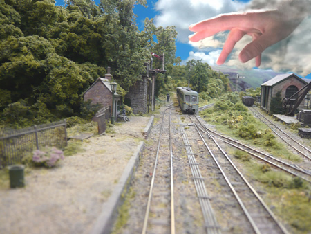
how to get 009 to work properly
(or how to avoid the 'Hand of God')
Like many other narrow gauge modellers, my
interest began with the adventures of the Craig and Mertonford Light
Railway of the late P.D.Hancock. I kind of just assumed that the layout would work
as well as it looked and was quite shocked to subsequently find that it
worked rather badly! I have to say that no other 009 layout has lit my
fire like the C&M ever since.
Apart from a very small number of excellent
layouts, in all honesty, the scale of 009 is now regarded by many as a bit
of a joke. The ultimate repository of naff little layouts in box files or
on pizzas with poorly made rolling stock that often derails and invariably
stalls. With a few exceptions, the scale has been used by those on a very
small budget, both in space, skills and funds. Those who have wished to get more
serious about their modelling have tended to drift towards larger scales.
The advantage of 009 is of course that due to
its small size, one can really concentrate on building a 'railway in a
landscape'.
The continental scale of H0e has fared much
better and if one likes the look of those ghastly European locomotives, a
generous selection is available off the shelf. The British market is just
too small to excite manufacturers enough to produce high quality RTR
British 009 stock and I rather suspect that many who use the scale do not
expect to spend more than a few pennies on a locomotive anyway.
One of the reasons why I built County Gate
was to show that a larger 'serious' layout could be built in this scale
which would run reliably. I would have to say that for the most part, I
have succeeded but with the perfect 20/20 hindsight that we all have,
there are plenty of things I would have done differently. Without doubt,
there will come a time when some things are upgraded in the light of my
experience but it will have to wait for a time.
So right now, some of my comments are more in
the 'do as I suggest' category rather than always 'do as I have done'!
The first port of call is the construction of
baseboards. These really need to be rigid and made of a material which
does not expand and contract (such as plywood). While many may lay track
on cork or Sundeala, I would suggest that the track should be laid
directly on 3mm plywood. This enables us to use 'wobblers' but more of
that later. The plywood needs to be well supported to prevent warping.
On larger layouts, you will need several
baseboards.
One of the essential requirements is to
obtain good register with tracks at the baseboard joins. We use cast
iron pattern makers dowels. These we buy from
Station Road Baseboards.
We fix the boards together with large
toggle catches from
Wixroyd. The silly little toggles sold for baseboards are quite
useless.
adjustable heavy duty toggles from Wixroyd
Once the baseboards are complete and fitted
together, we lay the track across the joint. The last 1" of the track at
the ends of the baseboards are set in epoxy resin. Once hardened, (24
hours) the track is cut at the joint with a very fine saw or cut-off tool.
Despite the fixing in epoxy, we discovered
that the lengths of rail would still expand in hot weather and foul at the
baseboard joint. We now add a second expansion gap cut in the track, 2"
back from the joint. This gap is .5mm. This is filled with epoxy. Since
then, we have not experienced problems.
Some solder the rail ends at joints and this
is also a valid method.
The most important issue is to ensure that
the track is as near as possible at right angles to the baseboard joins.
Oblique angles will cause nothing but problems.
One way around the problem of oblique angled
track is to use a removable section. This is not always possible however
if the joint is obscured by scenery.
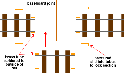
Another solution is to modify the baseboard
so that the joint is actually at right angles.
Most of us do not make our own track
although, I would have to say that if I ever replaced the track at our
station, I would do so now. Most of us use Peco track and the new 009
'mainline' flexible lengths look so much better than the previous 'crazy track'. The
problem arises with points. Peco 'crazy track' 009 points are frankly useless! The problem with the existing points is that they are not at all
accurate and are quite rough running. This is generally overcome by
'fettling'. 'Fettling' describes a process of modifying commercial track
to make it 'fit for purpose' and in my mind is not something we should be
having to do at all.
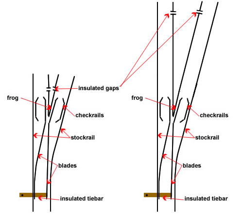
Always select live frog points.
My second gripe with Peco Crazytrack 009 points is that
they only have a radius of 12" Yes, they do 'Y' points at 18" radius but
they are also as rough running as hell. I strongly urge you to consider using Peco
Mainline 009 points which have a radius of 18". They are far more smooth
running and seem to be reliable. Some of you will be happy to
work with tighter radii due to space constrictions but even then, you may
prefer to consider using options other than 'crazy points'. Avoid double
reverse curves at all costs.
Many still favour using pins to fix track to
the baseboard. My experience is that it is far more likely to result in
track that is not absolutely flat. This will result in stalled locos, for
sure. I believe that the track should be assembled and soldered together
and then it should be glued directly onto the plywood. I use 20 minute
epoxy which gives ample time to align it correctly. When happy with the
positioning, I always place a piece of thick flat plywood on top and
weight it down until the glue has gone off. Do not forget to cut slots in
the baseboard in the correct positions to allow for point actuating rods
from under baseboard motors. Prior to fixing the track, also solder on
your electrical droppers and drill holes in the plywood to let them
through. Keep the holes to a minimum, otherwise you will lose your ballast
through the holes!
I always supply power to the track every two
feet. This will minimise voltage drop and will give you a good measure of
redundancy. The frogs of your turnouts will also require a dropper (use a
different colour code) so that you will be able to switch polarity. Make
sure that your droppers are colour coded. Do not forget to include
insulating fishplates at the frogs. Usually, I now place the insulating
breaks a little further from the frog.
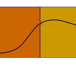
When aligning track, always try to build in
transitional curves as running will be vastly improved. Double reverse
curves without transition will cause trouble as long as they exist on your
layout.
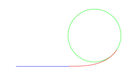
This is an example of a red transition curve between a blue straight line
and a green circular arc. The circular arc is supposed to start at the end
of the red easement curve.
Once you have fastened down your track, it is
time to test it with your rolling stock. Some commercial chassis (such as
Riverossi) have very deep flanges and it may be necessary to deepen the
flangeways at the frog and checkrails. In doing so, you will however
compromise some of the smooth running of the point. If you are able to
have deep flanges removed on a lathe, it is really worth doing it.
Hopefully, you will find that it all runs 'peachy'. If most of your stock
is happy with the track that is great. If one or two pieces baulk, rather
than butcher the track, look hard at the offending rolling stock. Most
likely, you will find that the back to backs are wrong. Adjust the stock,
not the track.
While I find that most 'crazy points' are
completely out of alignment, I have never found a Peco N gauge point to be
faulty, although I guess there is always a first time.
You may be needing some block sections. This
is the time to cut the rails for these blocks and solder a dropper to lead
through a hole in the baseboard. I always fill the insulating joint gaps
with epoxy to prevent expansion causing a short. Treat all soldered joints
with a saturated solution of bicarbonate of soda to neutralise your
soldering flux then lightly rinse.
You should then install any uncoupling
magnets that you require.
Once you are completely happy with the
operation of the track. I always suggest ballasting as soon as possible.
This will set the track firmly and prevent any subsequent movement. You
can then paint your track and weather it. Take real care not to scratch
the rail heads and make sure that paint is removed from the inside of rail
heads, as this is an important area for current collection.
You will be
making your choice of whether you elect to go with DCC or DC. It really
depends on whether you are a Luddite or not!
There is a simplicity to DCC as you no longer
have to worry about isolating sidings in order to stop the wrong locos
working as you choose the loco you wish to operate by selecting its
address. If the layout is already wired for DC, it will almost certainly
work for DCC as well, by the way. The only problem will be that you won't
be able to run another loco on one of the isolated track sections. This is
why I prefer to have the insulated joints away from point frogs as this
will prevent a DCC loco from becoming derailed if the point is set against
it.
A lot of rubbish is talked about DCC 'safe'
points. The only thing we have to do is to change the polarity of the frog
and blades when the running direction is changed. This means that the frog
must have insulated joints to prevent a short circuit. During the early
days of DCC, things were a bit different and shorts could weld a wheel to
the track. This is all changed now and the slightest short will be
detected and the power shut off before damage ensues.
Click on the switch below
to animate.
As far as I am concerned,
there is only one type of point motor.

Electromagnetic motors are
violent and noisy and are able to damage the cross tie of point blades. In
addition, the polarity switches are unreliable and it is very hard to
adjust the movement. Tortoise motors stall when the point is thrown. They
are gentle and have two excellent switches built in which will allow you
to change point polarity and even operate signals all at the same time.
You may find that the wire supplied with Tortoise motors is too flexible
to operate Peco points but is is quite easy to obtain a slightly stiffer
piano wire. It is also very easy to adjust their throw: the perfect
solution!
Now all you have to do is
to put the baseboard on its side and wire it up below. I used 6mm wide self
adhesive copper strip as bus bars which I purchase from ExpoTools. Apart from the
track power, you will also need bus bars to operate point and signal
motors.
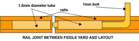
In service, for an
exhibition layout, I have found the copper tape to be very vulnerable to
tearing. I have moved to laying N scale track on the underside of the
baseboards. This is a far more robust solution to bus bars and is lower
in resistance.
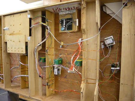
The hard wiring of County Gate station
nearly complete - click to enlarge

the replacement bas bars using N scale
track
You will need to jump from
one board to the next with your wiring. I have found D plugs to be very
reliable and can be bought with up to fifty pins.
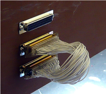
50 pin D plugs
If you have fewer wires,
another good solution is the DIN plug. You can get up to 8 connections
with these.
Some still use solenoid
motors such as produced by Peco and Seep. To 'save' costs, I installed
them in our fiddle yard and I have suffered many breakdowns. One problem
is that of polarity change of live frogs. The actual movement of the
blades is very small in 009 and it can be problematical to expect
mechanical switches to reliably change every time.
There is now a new
system with the silly name of Hex Frog Juicer (only in America!). This
is available from
Digitrains, in York. This unit will change 6 points at a cost of
£50 for DCC layouts. As the name implies its primary design function was
to automate frog polarity setting on 6 live frog points but the outputs
can also be configured in pairs to deal with reversing loops, wyes,
crossovers or any other situation where track polarity must be switched
to avoid shorts. Installation is simple and the unit can handle DCC
system and booster outputs up to a maximum of 10 Amps.
This is manna from
heaven as far as I am concerned.
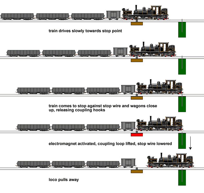
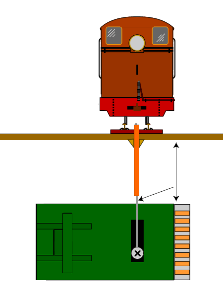
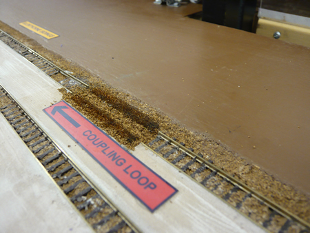
We use Greenwich couplings at County Gate.
First of all, we installed permanent magnets at strategic positions. They
were usually OK but we needed to be exactly over the magnet to get them to
work and that is easier said than done. Then again, the stock uncoupled as
often when not required as when we did! County Gate quickly became
populated with unnoticed stock which had detached from consists. Apart
from a four year old who thought this was really funny, the rest of us had
had enough.
The next attempt was using Peco
electromagnets. Naively, I thought, they are Peco.....they must work.
Stupidly I fitted the lot before finding that they could not pull off the
skin of a rice pudding. We now have electromagnets supplied by Wizard
Models which we have quickly nicknamed the 'black holes'. Despite their
apparent strength, these magnets were still inadequate to operate the
Greenwich couplers are they had been built.
Greenwich coupling etch
With the permanent magnets the couplings
operated when the lever arm was cut at position '1' and 8 turns of iron
wire wrapped around it. Our trains are largely held in fixed consists so
it has never been necessary to have every coupling operate. Where needed,
we cut now at position '2' and use 16 turns of iron wire. Care is needed
to ensure that the coupling does not foul any part of the vehicle.
With this mod in place, they will uncouple
but accurate positioning is necessary and double the iron wire is needed.
We have used independent 12V DC power supplies with these as it would be
folly to introduce the power drop to electronics.
For places where we need to uncouple at
exhibitions, (for us the coal train at the harbour) we have found that it
is still very difficult to stop the train at exactly the right spot every
time. There would then be a shunt back and forth until the correct
position was obtained.
Our solution is not for all because it
requires the locos to be of the same length. For us, not a problem as our
Garratt rules goods trains on the branch line. I decided that a physical
stop would be best and employed a Tortoise motor to do just that. Now, one
runs the train very slowly up to the Tortoise wire and we uncouple every
time.
|
when
all else fails .....the County Gate Wobbler |
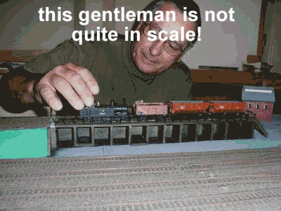
It is hard for men to discuss certain things
without falling about laughing. I'm afraid this is one of them!
How many of you have had to lean over your
layout and give a loco a shove? How embarrassing is it at an exhibition?
How often have you damaged a delicate bit of scenery doing it?
If the answer is YES to any of the above,
read on. If it is a NO, either you have never run a model railway or you
are completely delusional!
It all started while chatting with the
redoubtable Roy Link. The conversation got on to layouts and sound and Roy
mentioned that one of his friends has a large bass speaker under his
layout and never gets stalled trains. This got me thinking. County Gate is
actually what is disparagingly called a 'rabbit warren' layout. We cannot
afford to get trains stuck behind the scenes when we are going for
automation. The layout scenery gets damaged with large hands when trains
get stuck 'on scene' too.
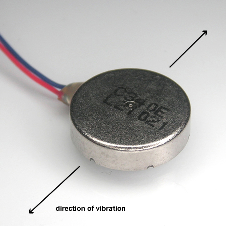
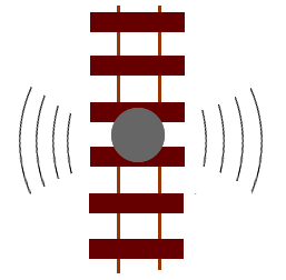
this is a 3 Volt 12mm Shaftless Vibration
Motor available from
Precision Microdrives
After a few trials, I glued a vibrator from
and old mobile phone under a section of track and it worked a treat! I
made sure that the wobble motion is from side to side, (90 degrees to the
rails).
Of course, you have to be sure that
everything on the layout is well glued down, and if you have laid on foam,
you are probably buggered. This is why I like solid attachment of the
track to thin ply.
Wobblers need to be fixed wherever you intend
to stop trains. Resisters were added to allow them to be run on 12 V DC.
Some may choose to use stronger vibrators.
Keeping the track really clean is the bugbear
of all small model railways. Some folks use Railzip or graphite pencils
with success but it can and does reduce traction.
Once the track has been painted and
ballasted, a lot of care is needed to remove any ballast that will foul
the wheel flanges. The scenic work is also very messy and considerable
effort is needed to remove debris and spray products from the rail tops.
For this we used a Peco track rubber which was pushed around with a 2
prong fork, to keep hands away from the delicate scenery. (Don't use your
wife's silverware for this if you wish to live long and prosper)
Continued maintenance is needed and the track
rubber leaves shiny debris on the track and scenery gets damaged nearly
every time.
Our first attempt to find a viable
alternative was a conversion of some American device which claimed
wonders. In a nutshell, a brass drum is wrapped in a bit of dishcloth and
soaked in track cleaner. This is supposed to rotate, dragging slightly and
clean the rails. The thing just derailed. I tried weighting it further and
it just derailed some more. In short, it was as useless as a
chocolate teapot.
At last the Japanese came to our aid!

We sold the BMW and purchased a Tomix 6421
track cleaner. We have fitted a Digitrax 123 chip to operate the motor.
There is a mini vacuum cleaner, debris being deposited in the centre
collector. It will suck up loose bits of ballast if running flat out.
There is also a sprung loaded rotating wheel which can be operated as a
dry polisher or wet, cleaner can be added to a reservoir. We find the wet
cleaner a bit useless, but the dry cleaner is perfect! In the UK, the
track cleaner is now available from Dapol.
It is not powered itself for running. I
wonder if it is that effective on DC as delivered power would depend on
the tow loco speed but on DCC it will run to full capacity.
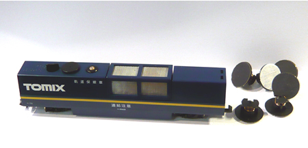
as it comes - click on
image to enlarge
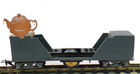
The boxcar cover for the
Tomix in Glenthorne Harbour Authority livery. - click on image to enlarge
The Tomix is the perfect solution to clean
all of the tracks prior to operating at an exhibition. However, we have
also found it worthwhile to clean the tracks now and then throughout the
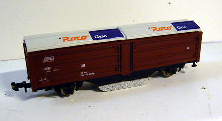
operating day. For this, we use our 'secret weapon Mk2; the N gauge Roco
track cleaning car (product number 25093)
This has a weighted rubber that is dragged
along between a 4 wheel chassis. Quite a powerful loco is needed for this.
We decided that it would be a good idea to produce a box car for the
railcar. It was built from a Nine Lines L&B boxcar with one end section
removed. Trusses were replaced using Plastic strip. Detail was sanded off
from the Roco wagon to be able to slide it inside the Nine Lines body.
As usual, the wheels were dipped in Carrs
metal blackening to bring them to a realistic colour.
The system works. The marks showing on the
rubber are from 3 circuits of the main line. The wagon is used regularly
during exhibitions to keep things running nicely.
showing the track rubber. This is easily
replaced
I have to say that I rarely clean
rolling stock wheels but loco wheels must be kept as clean as
possible to ensure good current collection.
In the end, I have built in to a siding of
the new fiddle yard a Peco wheel cleaner. Wired up to the tracks, it is
just so easy to keep everything pristine.
the built-in Peco wheel cleaner - click on
image to enlarge
If your track is not
perfect, whatever else you do, you will always be chasing your tail! This
becomes more and more important the narrower your track gauge is.
So now we come to the
rolling stock.
I am appalled to read that many exhibitors of
009 model railways feel that they need to bring three times as many locos
to a show to allow for failures. This is a damning reflection on the
reliability of the average unit. Then again, there seems to exist a blind
spot about 009 chassis. Time and time again I see quite attractive locos
which are then 'plonked' on top of an antique toy like chassis which often
as not can barely make a yard of running before breaking down. The owner
will proudly tell me how they picked up the chassis for £2 and just 'had
to do something with it'.
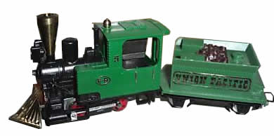
Jouef Egger-Bahn
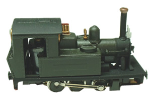
Peco kit on a Minitrix chassis - not a coupling rod in sight
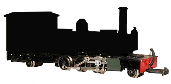
an otherwise nice outside frame prototype plonked on a Minitrix inside
frame chassis and what type of valve gear is that?
Indeed, the most common sight when watching
009 layouts is the constant prodding by large hands as these locos stop,
stick and waddle down the tracks.
Strange really, as N scale layouts can run
reliably for many hours without any troubles at all.
Until the appearance of
Backwoods
Miniatures, high quality etched loco kits were just not available. The
most common kits were white metal designed to sit on various commercial
chassis which usually had little in common with the prototype being
modelled. 009 owes a great debt to Pete McParlin who gave us ordinary
mortals the chance to upgrade our loco fleets without the need to scratch
build.
Sadly, only a select few are able to build
Backwoods chassis and make them run properly. Sadly, I am not one of them
but I have been fortunate to find someone who is able to build and upgrade
them to give good running and reliability.
Meridian Models also produce an excellent
outside framed version of the Baldwin gas mechanical and if you like the
small industrial stuff,
Nigel Lawton makes some exquisite tiny loco tractors.
A newcomer has arrived in the guise of
Victor Scale Models
whose first offering, the Sandy River No. 19,
looks like an excellent kit. They are following on with a Sandy River No.
22. This is now followed by a T130 Le Meuse based on a Grafar class 08
chassis.
Just announced is a proper RTR outside frame
chassis for the Penrhyn Port class. This is supplied by Parkside Dundas.
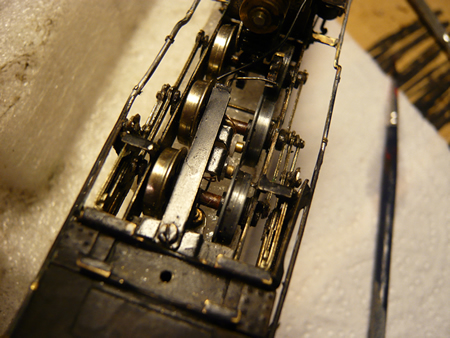
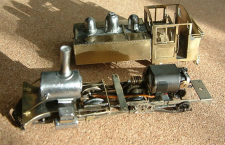
During the lean years, a number of successful
scratch built chassis were created nevertheless but the time and resources
needed to create them was excessive.
Bob Barnard began to build excellent 009
Lynton and Barnstaple prototypes complete with outside frames some 40
years ago. He has actually built every loco of the L&B fleet. He used
motors from Triang TT and they run extremely well to this day (but then
again, he is a bit good).
'Yeo' by Bob Barnard
Even I managed a Tasmanian K1 in 1972 when I
had access to all sorts of fancy machine tools and photo etching. It took
a year of spare time to make but runs perfectly to this day. So far, it
has logged over 500 hours of running.
K1 Garratt by John de Frayssinet
A small number of people are first class
micro engineers, almost watchmakers, and these folk can make the most
extraordinary chassis. Most of us ordinary mortals can only dream of the
skills needed to produce them.
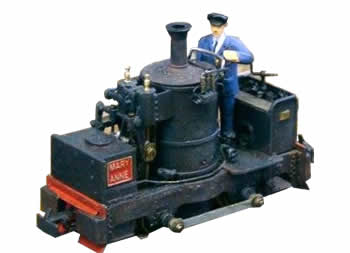
masterpiece in miniature with full working valve gear - de Winton
'Mary Anne' by the late Peter Smith. - photo Mick Thornton
The problem with scratch building is that the
time involved is far too much for most of us and leaves little chance to
complete a whole layout (Bob Barnard is an exception but he has been at it
for over 30 years!).
What we want is an easy way to obtain
realistic chassis to build onto.
|
so
what do we need to get a good running realistic chassis? |
Firstly, we have the problem of electrical
pickup. A four coupled chassis may very well work just fine on a clean bit
of test track but when placed on a scenic model layout, it is likely to
stall over and over again. With the best will in the world, your layout
will be unlikely to have perfectly clean track. A further problem may be
that in weathering the rails, the inside of the rail head gets painted
too. This can cause a real problem as electrical pickup is often through
the wheel flanges.
The next problem is if the chassis is not
perfectly square not all the wheels will touch the rails. The layout,
however may also have its defects so wheels can be suspended in mid air! A
sprung chassis is going to reduce this problem considerably.
So, you are most likely to have problems with
a four wheel chassis. The more 'feet on the ground' you have, the less
likely it will be that you have contact problems. Articulated locos are by
far the best for current collection.
Some have managed to build compensating
chassis which is a real advantage. This can result in pitching if the loco
is badly balanced. If the loco has long overhangs, a different
compensation is needed: see
the
wonderful modelling of Jeff Bissonnette .
fully compensated scratch built chassis by Jeff Bissonnette
Jeff states:
"The main problem with compensated
chassis', is that while they deal with rough track well in terms of
maintaining wheel contact/electrical conductivity, they don't deal with it
well in terms of visual grace. This is especially evident through poorly
constructed points, be it Peco OO9, or other commercially available
products. When operating through large flangeway, short pointed frogs,
compensated chassis' tend to do the "dive and jump", that is, they dive
down into the gap, then jump up onto the frog point.
The solution is to either construct your own points to a much higher
standard (which I do), or adjust the frog on commercial offerings (which
can be done by filling the flangeways with microstrip to a set depth).
|
how
is the electricity collected from the wheels? |
Without question, the worst place to collect
the power is through contacts acting on the wheel treads. Dirt will
inevitably collect on the treads and transfer to the collectors with the
result that sooner, rather than later, the loco will stall. Far better to
collect the power from contacts acting on the wheel rims or back of the
wheels. Sprung collectors are usual but very small plunger collectors are
available and are excellent.
Most modern chassis have insulated driving
wheels on one side only while the entire chassis is live with the opposite
polarity. This is now standard practice with say, Backwoods chassis. This
can have its drawbacks too. Great care is needed to make sure that pony
truck wheels can never touch the chassis.
Worse, some methods of installing couplings
means that they are live to the chassis. Unless you get it right, double
heading can cause a dead short. This means that you must always set up
your loco with a common polarity and never turn them around.
Another solution is the 'split chassis'
system. Here, the current is transferred through the axleboxes but there
are problems when scratch building to prevent the 'wrong bits of the loco
touching live bits' and thus shorting out. The axles of a full split
chassis system must also have an electrical break in the middle of the
axles. Thank goodness for Plasticard and epoxy glues!
The advantage of the split chassis is that
there is no resistance due to collectors acting on the wheels. The spacers
between the chassis frames also have to be insulating. The drawing below
is how I built the chassis for my K1 Garratt. For this type of chassis, I
use a conducting lubricant.
this Manning Wardle chassis has a 'live' side and plunger pickups on the
other
re-engineered Backwoods Baldwin chassis
One advantage of DC operation is that
electronic track cleaners can be employed. Quite often, a small resistance
between the wheels and rail are blown away with a micro jolt of high
voltage (they are also quite good for keeping your cat off the track).
If you are running DCC, you can programme an
additional start current which can often help.
Some products can be used on the track such a
Rail Zip or indeed a soft woodworking pencil. There can be wheel slipping
on gradients using some of these products.
If at all possible, flywheels should be built
into the model. Their size is going to be small to fit in the average 009
body but is often sufficient to help with smooth running and help the loco
through dead spots. Sadly, space just cannot be found in all locos, such
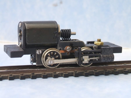
as in the Backwoods 'Lyn' shown above.
We all expect good slow running these days.
This will mean a gear train with accurate meshing of gears and good
bearings are an essential part of the formula. Some Backwood kits have the
motor worm drive slightly offset. While this may work, I have found that
excessive wear can take place.
Some specialist chassis are constructed in
such a way that it is almost impossible to take them apart to effect
repairs. The standard Backwoods chassis are exceptionally difficult for
instance. If at all possible, assume that everything will eventually wear
out and need replacing.
Some chassis designs are simply asking to
wear out due to their construction.
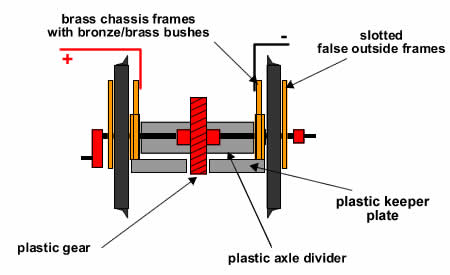
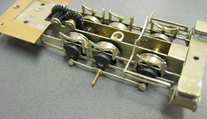
Firstly, let's look at the much vaunted
expensive Roco outside frame chassis.
click on image to enlarge
the Roco 'rip-off'
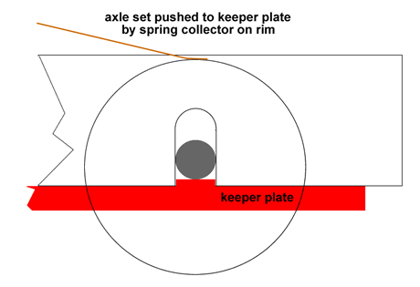
Here, the axles are not in bushes but make
point contact with the die cast chassis. Very quickly there is wear and
the loco will no longer run properly. The plastic keeper plate also slowly
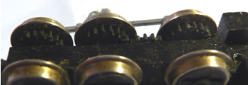
wears down. On top of all this, the Mashima motors supplied in the
loco very quickly develop a very rough spot when slow running. This is
another thing to look out for. These days, if at all possible, I remove
motors and run them light. In my view, there just should not be any rough
spots at all.
For reliable running, axles must be fitted in
proper bushes in brass or better still, bronze.
a properly bushed chassis by Victors Models (Sandy River No 19)
Equally, coupling rods and crank pins will
wear. This is particularly the case with chassis that are driven through
one axle as is the case with the chassis shown above. I now favour hard
steel crank pins and bronze bushes sweated into the coupling rods. If you
think this is a tad over the top, our first Backwoods Manning Wardle wore
out its crank pins and rods after 20 hours of operation.
This leads us on to the next issue. If only
one axle is driven, it is far far better to drive the centre axle in a six
coupled unit rather than an end one, as shown above. There is far less
binding and likelihood of wear. In my view, the best solution is to drive
all coupled wheels.
The Early Lilliput chassis did this and will
run forever given simple maintenance. True, they run too fast and the
motor is not the best but the coupling rods do not do any work so they can
be reduced to scale size with no concerns. My Baldwin, which has such a
chassis and is fitted with scale sized rods, ran 24/7 for a year in a shop
window. It still runs great now!
early Lilliput chassis
One chassis which potentially fulfils all the
requirements is the new
N Drive
Productions unit. They even
promise to offer them with outside frames. True, no
valve gear comes with it, but this is easy enough to add, using a fret
available from Backwoods Miniatures at £18. The drawback is that at
present, their construction is a part time job and as they become more
popular there might be some delivery delay. Hopefully he will find ways of
increasing production.
N Drive
Productions 6 coupled outside
frame chassis
0-4-0 chassis by
N Drive
Productions (£42)
I have always tested my chassis for 8 hours
running forwards and a further eight backwards, If any sign of wear showed
after this ordeal, the design would be re-engineered. That is, until I
bought the Roco chassis, which I assumed had been previously rigorously
tested. How wrong I was and the whole exercise has cost me hours of work
and £400!
By the way, it is worth keeping logbooks for
your locos so you can record the hours they have run.
There are, of course, those who just like to
collect locos...lots of them. But for those who are building a layout and
want their locos to look as good as possible, is it not time to take a
long hard look at the quality of running chassis? Costs are coming down
but there is no doubt that 'proper' locos are going to be more expensive.
What would you rather have, numerous toy trains or fewer proper models?
I have got thoroughly fed up with 009 bogies
and wheels supplied in kits. They are not very free running, often
inaccurate and if one is able to get them working, they can be very
delicate.
Mass produced N gauge equipment is, on the
other hand, very reliable. Simple solution...use N gauge gear. Our Lynton
and Barnstaple narrow gauge rolling stock sits on the rails rather like
sausage dogs - you really can't see the undercarriage! I hear anguished
purists bemoaning the use of such gear, but they are often same folks who
spent a lot of their time putting things back on the rails!
I have selected bogies produced by Green Max,
supplied by
Wellington Models, Somerset or from
Hobby
Search. We use DT 22 bogies for goods and DT 16
for coaching stock. The wheel bases are a bit shorter, which allows one to
place the bogies between the frames, where they are supposed to be, and
still get sufficient movement for 12" radius turnouts. At present,
there seems to be supply difficulties with Greenmax.
I have never found a Green Max wheel out of
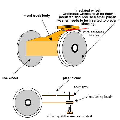
'back to back' but I do check every one with a gauge. The additional
advantage of Greenmax wheels is that only one wheel is insulated so they
can also be used for current collection. I just pull out the knuckle
coupling and glue in a Greenwich version.
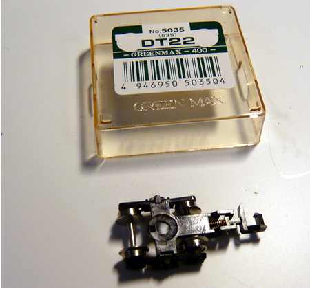
Green Max
goods bogie
|
getting power to the locos |
Many of our locos have small wheels and not
enough of them to be able to reliably collect current at all time to run.
In order to get more wheels to supply current, pony wheels can be used as
well as the drivers. The simplest method is to use just one wheel each
pony truck. With Greenmax wheels, this is simple.
Another method is to use the adjacent
wagon/coach as a current collector. Often, locos remain as a fixed consist
so under these circumstances this is a very good option. All our main line
trains that run under automation are connected to companion cars. The Greenmax bogies have
self adhesive copper tape fastened to one side of the bogie frames. This
will pick up the current from the uninsulated wheel.
Some plastic bogies, such as those supplied
with Nine Lines kits do not take kindly to having metal wheel sets fitted
as there is too much tension. By using these inserts, a really good low
friction bogies results.
The connectors used are supplied by Express
models. Another advantage is that is is very easy to test a loco on DCC by
just plugging in with a lead.
Once you have soldered on the correct wires,
you will need to encase the joint in epoxy, otherwise the joint will break
in time.
The choice of wire as connectors is
difficult. They do have to be very soft and flexible. The best is that
supplied by DCC Supplies. They use it for DCC chips.
The plugs are inserted with tweezers and are
marked with a small spot of paint to ensure correct polarity.
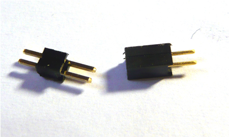
micro connectors supplied by Express
Models
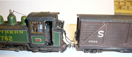
'Lyn' and her best friend!
I always advocate using 'companion cars'
connected to locos that run with fixed consists. The additional current
collection makes these trains almost 100% reliable. The problem at times
is that the bogies of the companion car are far better at collecting
current than the rigid chassis of the locos themselves. After a period of
operation, the locos become very reluctant to operate on their own.
Careful cleaning is needed and after a little coaxing, they will begin to
run again. I always let them travel a few circuits in both directions on
their own before reattaching to the companion car.
Despite best efforts, occasionally we find a
piece of rolling stock that just will not stay on the rails.
-
Check back to back
measurements on all wheels
-
Is there a lump of say,
glue, attached to a wheel tread?
-
Are the couplings
sticking against the body or not giving sufficient movement side to side
where there are derailments?
-
If bogies, is there
enough room for them to move sufficiently?
-
Is the stock heavy
enough?
-
Are the wheel sets/bogies
in line? Check the vehicle on a sheet of glass
If none of these things
work sell the railway!

|