|
model railway wiring
Wiring worries many modellers but it only has
to be as complicated as you choose it to be and actually can be a
fascinating part of the hobby in itself. I shall not discuss sophisticated
systems as those who wish to go down that route will already have their
own ideas.
These days, one is frankly, in my opinion,
foolish not to elect to choose digital command control (DCC). This system
offers far better controllability and simplicity.
You will need a small soldering iron, stand
and thin resin core solder.
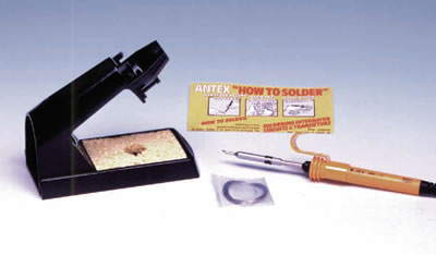
starter kit from EXPO
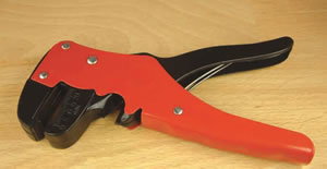
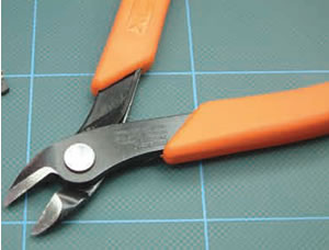
Tools
wire strippers and cutters
Small diameter heat shrink wire wrap, which
can be bought at shops like Maplins, and of course rolls of wire of the
required colours (five colours minimum). The wire should always be
multi-strand. Seven strand 0.2mm is nearly always sufficient.

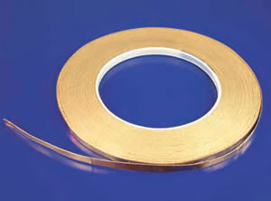
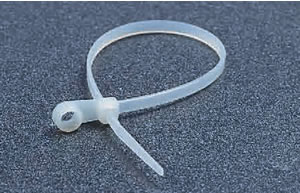
You will also need a roll of self adhesive
copper tape for the under board bus bars and small cable ties. We have
found this method satisfactory for small simple wiring but on larger
more complex layouts, I now use N scale track glued on the underside of
the baseboard as a bus bar. It is far more robust and has less
resistance.

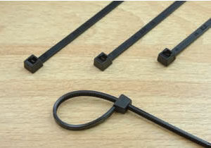
you can use these fellas
to screw to the underside of the baseboard
All the materials can be purchased from EXPO
Tools, All Components or similar supplier.
You should always solder electrical contacts.
making sure that a proper joint has been achieved. Try to keep the wiring
neat without too much excess of wire length. You can make up bundles which
are attached to the underside of the baseboard. Leave the cable ties loose
and thread through each wire until you have finished. You can then tension
the ties.
I am going to assume that the baseboard we
are describing is to be self contained. This will mean that various power
supplies have to be installed. These can be quite heavy so it really is
worth while making the rest of the model as light as possible. Provided
that the transformers are certified as double insulated, It is acceptable
to install under the baseboard provided that there is a reasonable passage
of air, for cooling. I tend to fix these things using cable ties.
1. If you are going DCC, you will
require a special power unit. It is foolish to use this transformer for
any other purpose. I no longer fit mains transformers in the baseboards
and prefer to leave them on the ground with a low voltage connecter to
the baseboard.
2. You may require another 12V DC power
source and even a 15V AC source as well, depending upon what ancillaries
you intend to install.
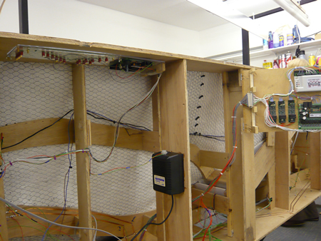
a transformer under one of our baseboards
- copper bus bars can be seen running along the framework We now place
transformers on the ground with a low voltage connecter to the board.
The mains wires from the transformers need to
be lead to a position on the baseboard where a socket is to be installed.
I use kettle plug sockets set into the baseboard side. The mains wire
junction is encased in silicone mastic and the rear of the socket
protected with a blue painted plywood cover (blue denotes mains wires). I
never lead the mains wires in the same bundle as low voltage wires.
You will of course need a switch panel if you
wish to operate any points or signals. I make these from two sheets of
clear acrylic cut to shape. The graphics are generated on computer and
printed out. We use small double throw double pole switches supplied by
Expo Tools.
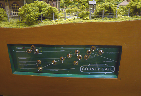
a switch panel on County Gate - This
panel has now been removed from CG.
You may elect to set your DCC controller into
the baseboard side as we have done. It is held in place by Velcro and
therefore easily removed. The wires entering into the controller are
easily unplugged.
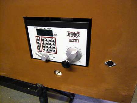
This shot clearly shows how our Digitrax
Zephyr is set into the baseboard side.
We now have to fasten self adhesive copper
tape underneath to act as bus bars for the wiring. This is by far the
easiest method I know as it is so easy to solder on droppers from the
track and ancillaries. We source ours from
Expo Tools. For a
more robust solution, use N scale track as mentioned
above.
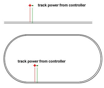
One pair of bus bars will supply track power.
You can then solder the red and green droppers from the track to the
requisite bars.
Make sure that you choose different colours
for your wires, say, red for positive and green for negative. If this
consistency in polarity is not maintained, you will have short circuits.
If positive rails are connected to negative rails, for example, nothing
will work, and even worse, your equipment might be damaged. In its
simplest form, wiring a track could not be more easy! The track power
supply
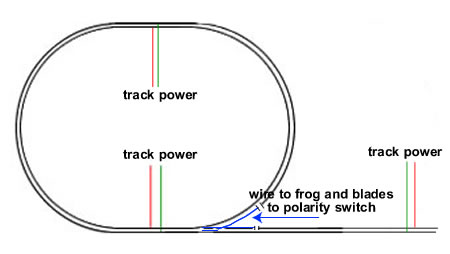
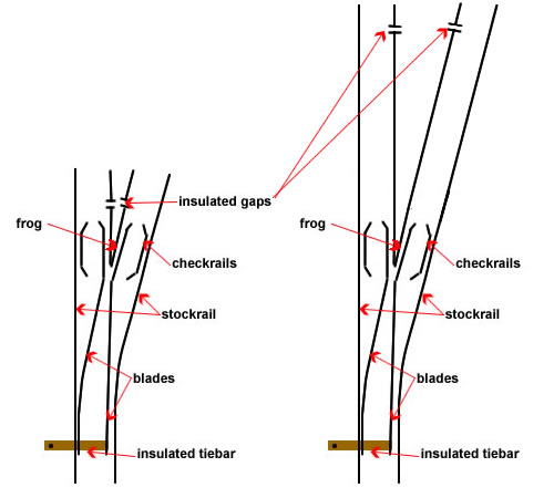
The problem arises once we add any points to
expand the layout. The frog (shown in blue) must change polarity. Track
power should be supplied to the rails every 600 mms from the under
baseboard bus bar in order to prevent voltage drop.
If you are purchasing ready made pointwork,
you will find that there are two kinds; live and insulating frog.
Insulating frog points should never be used so you are going to have to
change the polarity of the blades and frog when the point has its
direction changed or the blades will cause a short circuit in one
direction.
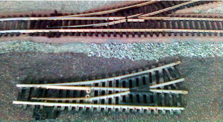
the dreadful Insulfrog
effort is the one at the bottom!
You will also have to install a point motor
under the baseboard in order to actuate the blades. This will allow you to
route trains remotely from your control panel. Some folks use mechanical
means to do this but frankly, I do not recommend it.
Unlike DC wiring, the track remains
live throughout at all times. The downside is that it is only too easy to
drive a train into a point that is set against it. This can be prevented
by extending the length of the isolated sections of the frog.
This is the simplicity of DCC as you no
longer have to worry about isolating sidings in order to stop the wrong
locos working as you choose the loco you wish to operate by selecting its
address. If the layout is already wired for DC, it will almost certainly
work for DCC as well, by the way. The only problem will be that you won't
be able to run another loco on one of the isolated track sections.
The only thing we have to do is to change the polarity of the frog
and blades when the running
direction is changed. This means that the frog must have insulated joints
to prevent a short circuit. Click on the switch below to animate.
DC
turnout
- click on switch to
operate
Despite many articles that describe 'DCC
Friendly' points, I do not bother to install them. If you are using Peco
'Crazy track', it would be very difficult to convert to 'DCC friendly'
anyway.
Just to explain what DCC friendly points are.
Some people are concerned that when running DCC which has a slightly
higher voltage (15VAC), a wheel might short circuit between the blade and
stock rail, so they add an additional rail break so the the blades are
always the same polarity as the adjacent stock rail. Indeed, learned
articles abound on the web about 'friendly' points. Again, click on the
switch to see operation. I find that it is quite unnecessary to go to all
this trouble and I think one is more likely to damage the very delicate
small points. A few locos or bogies may indeed touch the wrong polarity
blade and cause a short circuit. This is quite rare and the first thing to
do is to check the back to back measurements again. The worst offenders
are Riverossi power bogies which have flanges deep enough to cut into the
Earth's crust. The only solution is to give two coats of varnish to the
backs of the wheels (I use Ronseal). Once hardened, the problem has gone.
DCC 'friendly turnout' -
click on switch to operate
These days, I can only recommend point motors
supplied by Tortoise. They are adjustable and have
excellent polarity switches. The actuating wire is controlled by a motor,
so the point change is slow and silent and puts far less strain on the
point than the violent solenoid motor (Peco). The full PDF file for installation can be
found here. If there is a
depth problem under your baseboard, they can be fitted on their sides and
the actuating wire bent to suit. We find the wire supplied for the
actuator is too flexible to operate the blade springs on Peco points and
therefore use a slightly heavier wire. The connectors are simple to solder
to. I tend to glue the motors into position with 5 minute epoxy. To
ensure that they are correctly positioned, they are first wired up and
operated while the glue is setting, the motor being nudged one way or
another to get the best operation.
A Tortoise installed. The arrow points to
the throw adjuster which can be slid up or down to suit
The diagram below shows the wiring for two
point motors. The double pole, double throw (DPDT) switches would be
mounted in the control panel.
There are two single pole double throw (SPDT) switches
built into the Tortoise motor. One will be
required for changing the point frog polarity while the other can be used
for operating signals, etc. It is not always easy to work out which
terminals the track power should be connected to, so that the frog changes
to the correct polarity. I tend to do one at a time and test the
operation. If there is a short on track power, then reverse the red and
green wires!
The signals should also be connected at this
time. These may be interlocked with the Tortoise motors by leading wires
from terminals 5,6 and 7 to the signal motor.
|
Peco
motors, if you must! |
So lets look at the installation using Peco
point solenoids and polarity switch. Firstly, I solder a 'dropper' (a thin
length of wire) soldered on the underside of the frog. Once the exact
position of the point has been established, drill a hole in the baseboard
to allow the dropper to pass to the underside and drill a slot to give
adequate clearance for the actuating rod which passes through the hole in
the tiebar. The point is then fitted and fastened down (I just epoxy them
onto the baseboard). The fishplates are soldered to the adjacent rails but
do not forget to use insulating fishplates on both sides of the frog.
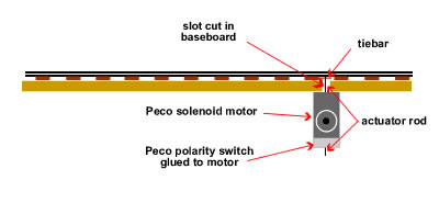
I then temporarily wire up the solenoid
including a switch and then epoxy the motor to the underside of the
baseboard. I make sure that the blades are held midway between the stock
rails and that the actuating rod is at the centre of the slot. As the glue
begins to go off, I operate the point and adjust if necessary to ensure
that there is an equal throw and that the blades go fully over.
Once the glue has gone off, I add the
polarity switch which I also glue on.
-
Make sure that the motor
is placed at the centre of the throw. If it is not, you will see the
actuating rod bounce back toward the centre. If this happens, the
polarity switch will not operate.
-
If you do have to remove
a glued solenoid motor, a couple of light taps with a chisel will release
it.
You are then ready for final wiring. The Peco
solenoid motor is operated through a Capacitor Discharge Unit (CDU). This
gives a good belt of electricity which powers the solenoid. CDUs are
powered from a 15V AC transformer. You must use a momentary contact switch
as holding power onto the solenoids will burn them out. Click on switch to
operate the image below.
Polarity
switches have not stood the test of time for both Peco and
Seep products. These days, I use Hex mono juicers and let
the electronics change frog polarity all on their own!
The Peco turnout maintains blade position by
a small spring hidden near the tie bar. These can fail and the system will
no longer properly hold the blades in place. If this happens, you can
replace the Peco motor with a latching Seep motor which is available from
Gaugemaster. The wiring is the same.
These days, if I must use solenoid motors, I
choose self latching Seep units. The spring in the Peco point is
removed. The advantage is that much less power is needed to throw the
point and it is less likely to eventually come to pieces.
The point motors can also be operated by DCC.
If this is done, each point will need a decoder which is not cheap. This
is done on County Gate because the operation is automated.
|
wiring slips, diamond crossings, three way points and
crossovers |
Wiring these
beasties for DCC is now a breeze. Just install a
Hex Frog Juicer and let it do all the work for you!
|
wiring slips the hard way (our thanks to Southern Digital) |
The information having to do with frog
polarity reversal is irrelevant to Peco InsulFrog turnouts. The
information about track connecting to the slip having the correct polarity
is applicable to any slip, no matter how it’s made or who makes it.
A slip (single or double) has two frogs. For an ElectroFrog slip to work,
polarities must come to the slip correctly, and the frogs needs to have
individual polarity reversing capability. In most cases it’s all fairly
easy to do - especially with DCC. There are four wires coming from the
bottom side of the double slip - one from each frog. The wires are
imbedded in grooves in the ties.
A slip, single or double, requires certain things for it to work. This
includes polarities being correct, and a way to reverse the polarities of
the frogs when needed. Whether it’s a single or double slip is irrelevant
when it comes to polarities. They are both installed and handled in the
exact same way. The only difference is that there is only one slip to
allow transition from one route to the other. Regardless, both frogs and
all routes have to be considered. We’ll first show how a double slip needs
to be installed, then explain how to deal with polarities.
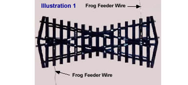
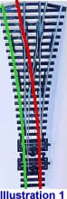
Illustration 1 shows the rails that are fed by each feeder wire. The two
blue frogs are separate, each with its own feeder. The red indicates the
rails that are fed by the feeder going to the top stock rail, while the
green shows the rails fed by the bottom stock rail feeder. The frog feeder
wires must be used to control the frog polarity, and insulated rail
joiners must be used to connect the adjoining rail to them.
The stock rail feeders can be used to power
the stock rails, or the stock rails can be connected directly to the
adjoining rails with metal rail joiners. There are four wires (feeders)
coming from the Peco ElectroFrog Slip: one from each frog, and one from
each stock rail.
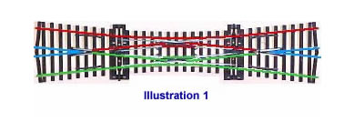
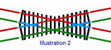
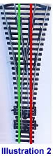
Illustration 2 shows that the polarity of the
rails joining to the slip must match the polarity of the slip’s stock
rails.
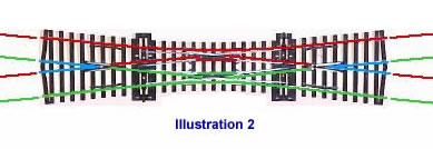
You can see that this will be connecting both
polarities to each frog, which is why those rails must be connected with
insulated rail joiners.
If using DCC, there are two ways to control the polarities of these frogs:
auto-reversing, or external contacts connected to each throw bar.
If using auto-reversing, you can use two Digitrax Auto-Reversers (D-AR1)
or two of the four outputs of a Digitrax PM-42 (D-PM42). If using the
D-AR1, connect one output of one D-AR1 to one frog, and one output of the
second D-AR1 to the other frog. If using a PM42, connect one wire of one
output to one frog, and one wire from the second output to the other frog.
It doesn’t matter which output wire you use, as long as you use a separate
auto-reverser for each frog. In any case, it will auto-reverse when a
short circuit is sensed at either frog.
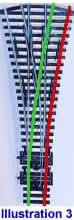
If using external contacts, you have to realize that the throw bar on one
end of the slip needs to control the frog on the other end of the slip.
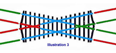
Illustration 3 shows how to do that.
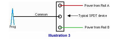
This could be Peco contacts mounted on a Peco
switch motor, a SPDT micro switch mounted to make contact with the throw
bar, or any other common Single Pole Double Throw (SPDT) device. When the
throw bar is one way, it feeds power from Rail A,; when set the other way
it feeds power from Rail B.
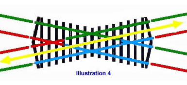
Illustration 4 shows a situation that will
have to be corrected before you can make the slip work correctly.
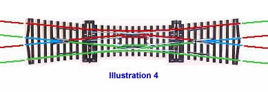
Notice that the track coming into the double
slip from the upper right doesn’t have the correct polarity. This means
that you have a reverse section somewhere on the layout that hasn’t been
resolved, and will not work. To fix this, you need to go back on that rail
and install a reverse section so that the polarity comes into the slip
correctly.
There are many variations of this, but regardless of what the situation
is, the polarity must match as shown in Illustration 2 above. Note that it
doesn’t matter what the polarity is as long as it matches in all
directions. Once it matches, resolve the frog polarity as described above.
Again, with Peco InsulFrog Slips, you do not have to be concerned about
reversing the polarity of the frogs. But you do have to be sure the
polarity of tracks attached to the slip is correct.
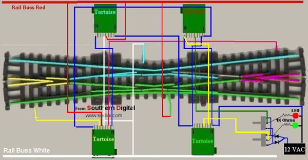
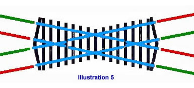
Illustration 5 shows you how to wire your double slip switch using
Tortoise contacts to route the power to the rails properly and adding LED
indicators.
|
wiring diamond crossings the hard way |
The information having to do with frog and
crossover polarity reversal is irrelevant to Peco InsulFrog crossings. The
information about track connecting to the crossing with the correct
polarity is applicable all crossings, no matter how it’s made or who makes
it.
A crossing has two frogs. How the polarity comes into the crossing will
determine whether the frog or the rest of the crossing needs to flip
polarity. Regardless, in most cases it’s easy to do — especially with DCc.
As you can see in Illustration 1, there are
two wires coming from the bottom side of the crossing; one from each frog.
The wires are imbedded in groves in the ties. If you’re running DCC you
can use a Digitrax Auto Reverser or one output of a Digitrax PM42. That’s
what the rest of this dialog will address. If using DC analogue control,
you’ll have to handle it in the traditional way — with toggle switches.
The first of four situations is where the
polarity comes into both ends of the crossing with opposite polarities to
the frogs, as shown in Illustration 2 at right.
Notice the rails that connect to the
crossing’s stock rails are of the same polarity. But the rails that
connect to the frog rails (blue) are two different polarity. This is the
easiest situation to handle. Simply connect one frog to one output of the
auto-reverser, and the other frog to the other output of the
auto-reverser. Be sure to use insulated rail joiners on all four frog
rails. You can use metal rail joiners on the stock rails.
The next situation, shown in Illustration 3,
is where the polarity comes into both ends of the stock rails with
opposite polarities. In this case, the stock rails become the reverse
section. Connect the frogs with metal rail joiners, connect the stock
rails with insulated rail joiners, connect one output of the auto-reverser
to one stock rail (blue), and the other output of the auto-reverser to the
other stock rail (blue).
The third situation, shown in Illustration 4,
is more complex. It involves coming into one end of the crossing with like
frog rails and the other end with like stock rails. That’s because you
have a reverse section somewhere on the layout that hasn’t been taken care
of.
Since there are two blue (reverse) sections,
one might quickly think that all that needs to be done is to connect each
one to an auto-reverser. But notice when travelling the yellow route that
the polarity changes from one side of the crossing to the other. While the
frog rail could change to red without any problem, the stock rail can’t be
red and green at the same time. Even if it could, when a loco spans the
crossing from one connecting track to the other, it would cause a short
circuit.
In this particular situation you need to take care of the reverse section
needs elsewhere to make the track polarity come into the crossing to match
one of the previous two examples. Taking care of the reverse section on
the lower left track would create a situation like in Illustration 2 —
preferable. Taking care of the reverse section on the upper right track
would create a situation like in Illustration 3 — not preferable, but
easily handleable.
The fourth situation, shown in Illustration 5, is similar to the last one,
in that there are reverse sections elsewhere on the layout that haven’t
been taken care of.
Notice that the difference between this and
the last situation is that no matter which route you take, the polarity
reverses on the other side. This means that more than likely you have two
reverse sections to fix elsewhere on the layout. To make handling the
crossover polarities as easy as possible, it’s best to take care of both
reverse section needs from the same end of the crossover. Doing this will
make the stock rail polarities the same, and leave only the frogs to make
reversible (with insulated rail joiners).
Again, polarity reversal is not applicable to Peco InsulFrog crossings,
only to live frog crossings.
|
wiring three way points the hard way |
3-way ElectroFrog turnouts have a unique need
for controlling frog polarities.
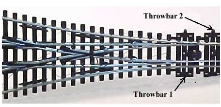
As you can see with the photo above, there
are three frogs: one right in the middle, and one on each rail of the
middle route. With Peco ElectroFrog 3-ways, the upper frog and the frog in
the middle are connected together to one feeder wire. The lower frog has a
feeder wire of its own. You can also see that there are two throw bars.
We’ll call the throw bar closest to the end #2, and the other one #1. So,
with just two feeders and two throw bars, how do you control the polarity
of three frogs? Simple. Since only two frogs are used at one time, there
is always one frog that is not used — no matter how the throw bars are
set. Check the illustrations below to see how polarities work with the
various settings.
|
|
|
|
|
|
Train
|
Going left
|
Going straight
|
Going right
|
|
Left frog
|
Red
|
Green
|
Irrelevant
|
|
Centre frog
|
Red
|
Irrelevant
|
Green
|
|
Right frog
|
Irrelevant
|
Red
|
Green
|
|
Throw bar #1
|
Right
|
Left
|
Left
|
|
Throw bar #2
|
Right
|
Right
|
Left
|
In Illustration 1, both throw bars are to the
right, making the train go left. You can see that the left and centre
frogs are both of the red polarity. In this situation, the polarity of the
right frog is irrelevant.
In Illustration 2, throw bar #1 is to the left and throw bar #2 is to the
right, making the train go straight. You can see that the left frog has
green polarity and the right frog has red polarity. In this situation, the
polarity of the centre frog is irrelevant.
In Illustration 3, both throw bars are to the left, making the train go
right. You can see that the centre and right frogs are both of the green
polarity. In this situation, the polarity of the left frog is irrelevant.
At no time do the centre and right frog have to have different polarities.
They are either of the same polarity (Illustration 3) , or one or the
other is irrelevant. This is how the right and middle frogs can be tied
together to have the same polarity. So, all we have to do is figure out
how to control the frog polarities with the two throw bars.
By using a set of Single Pole Double Throw (SPDT) contacts on the switch
motor, or a micro switch on throw bar #2 (the bottom one), we can control
the middle and right frogs. When throw bar #2 is to the left, it will feed
green polarity to those frogs so the train can go to the right. When throw
bar #2 is to the right, it will feed red polarity to those frogs so the
train can go straight or to the left.
By putting a set of Single Pole Double Throw (SPDT) contacts on throw bar
#1 (the upper one), we can control the left frog. When throw bar #1 is to
the right, it feeds red polarity to the left frog so the train can go to
the left. With throw bar #1 to the left it feeds green polarity to the
left frog so the train can go straight. If the train goes right, the left
frog is not used, so it is irrelevant.
Wiring on model railways can get very
complicated very quickly. It is most important to keep track by drawing
out good wiring diagrams. I have always done this by computer and posted
them on my website so that they can be easily accessed if we are away on
exhibition.
see here
So after all of that, you should have a
baseboard with operating points, frogs which have the correct polarity,
signals that work and track power from your controller throughout. There
are of course other things which you may wish to install at this time such
as our 'wobbler
system' or some form of electric uncoupling system. Once you are happy
with it all, it is time to turn over the baseboard and check that it all
works correctly.
Start running train around and hopefully you
will have to make few adjustments to ensure that operation is perfect.
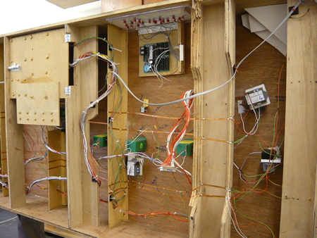
a baseboard with wiring complete - point and signal motors can be seen as
can the copper bus bars


|