|
the viaduct step by step
While much of this information is also copied
elsewhere, we thought it might be useful to show how this module was built
step by step.
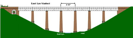
projected viaduct design -
click to enlarge
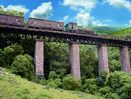
'River Avon' hauls a goods to
Lynton
over the newly completed viaduct section
- click to enlarge
click to enlarge
|
the
build - using Wills plastic building sheet |
We have spent a great deal of time discussing
the design of the viaduct as it is such an important element of the County
Gate layout. Finally, we decided that we did not want to have a 'Chelfham
structure' as this had been modelled so often already. The
open structure of the lattice girders will allow the trains to be much
better seen and the girder lattice has very good visual impact. We
want the trains to 'teeter' across it! A deceleration circuit will be put
in place on the viaduct.
I am fortunate in having a civil engineer son
who did rough calculations to confirm that the full sized structure would be safe
and an appropriate design of the period for
the prototype loads.
The plastic building sheets produced by Wills
are a fantastic aid to scratch building. Some special techniques are
needed to make sure the resource is best used.
-
The material is slippery
and it is very hard to hold a steel rule in place while cutting. We use a
steel rule that has has fine sandpaper glued to one side. This stops
those embarrassing errors with the knife.
-
It is important to use
sharp cutting blades. They become blunt quite quickly when hacking at
this hard material. As the point loses the edge, we break off the tip to
expose a new cutting edge.
-
When cutting a sheet, two
passes of the blade is usually sufficient to score the plastic enough to
be then able to snap off the part by bending.
-
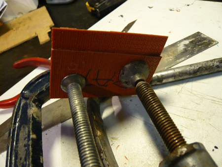
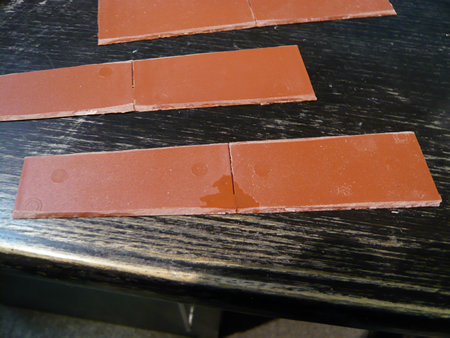
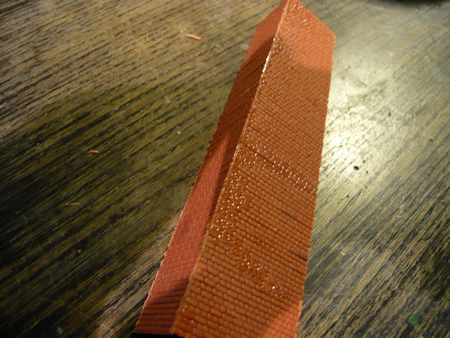
When making the viaduct,
we had many surfaces to cut which were at an angle. We used one sheet of
plastic as a pattern, and cramped it on to the sheet to be cut to prevent
any slippage.
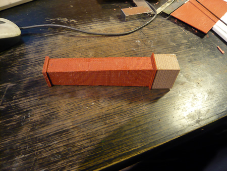
These are the underside of the viaduct piers. The mitring is clearly seen
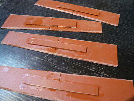
the but joints are
reinforced using off cuts. While the glue is still slightly soft, make
sure that the face surfaces are accurately in line.
-
When gluing, coat both
mating surfaces a couple of times, then run more Plastic Weld into the
joint from behind. It is important that glue does not migrate to the face
as detail will be lost. After a few minutes, the plastic is sufficiently
soft to be able to gently 'wiggle' both surfaces together so that any
irregularities are filled by molten plastic. Make sure that brick
courses, etc., are in line. We often add triangular bracing pieces to
strengthen the joint.
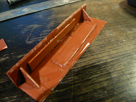
construction of viaduct
piers
Here, the final side has
been added. The mating surfaces still need to be nudged closer together
while the plastic is still soft
-
When the joint has fused,
but is still very slightly soft, we run a sharp blade across the corner
to remove any excess plastic. The brick joints are then extended round
the corner using a lightly applied blade which is rocked side to side to
expand the joint to the correct width.
the completed pier
-
Observe with care
bricklaying techniques used on the prototype. Fancy brick courses can
easily be cut from the sheet. If you wish to have curved bricks, the
profile can be sanded and the brick courses added with the craft knife.
-
We prefer to build Wills
arches flush into the sheet. This means accurately cutting the sheet. For
this we use a Dremel cutting disc. The final fit is done with careful
paring with a knife.
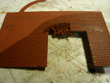
The bridge for the
harbour branch under the South abutment.
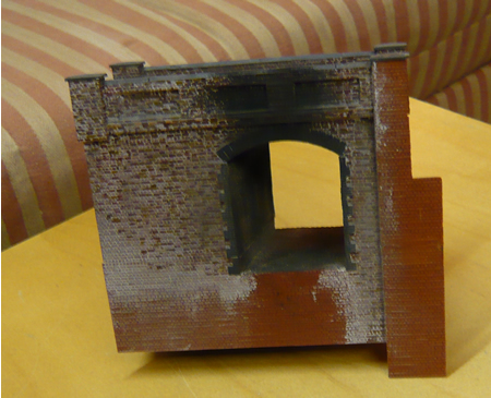
Partially complete South
abutment
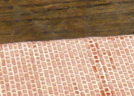
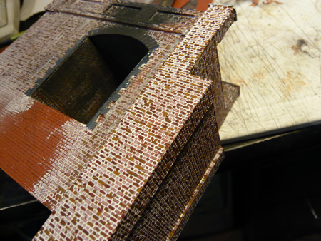
Brickwork picked out with
three colours.
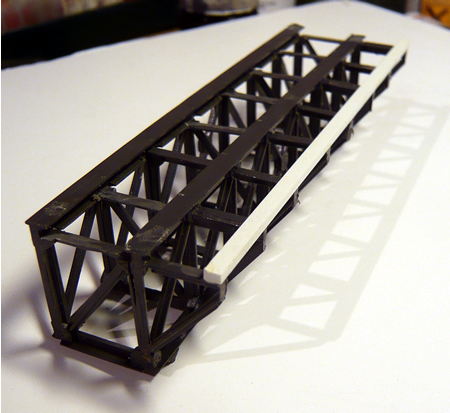
The trusses are made from
Peco N scale girder bridges. 2 packs are needed for each truss, (8 sides)
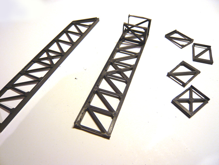
the trimmed truss
sections - click on image to enlarge
cross members are
fabricated from other trusses
- click on image to enlarge
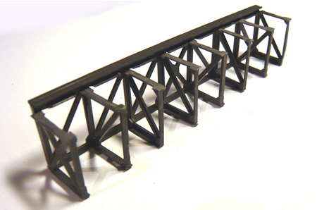
Once the truss is
fabricated, the foot walk canter levers are cut from spare trusses. Each
end is first fitted and joined with the 'timber balk' and the others are
fitted afterwards. Care is need to ensure all is square.
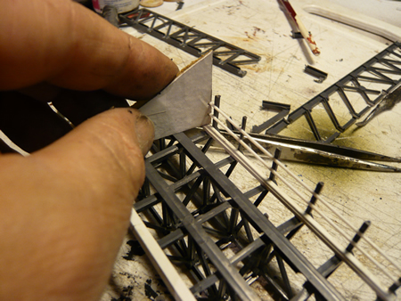
Handrail stanchions are
also made from parts of the spare trusses and the rails attached using the
jig shown above.
- click on
image to enlarge
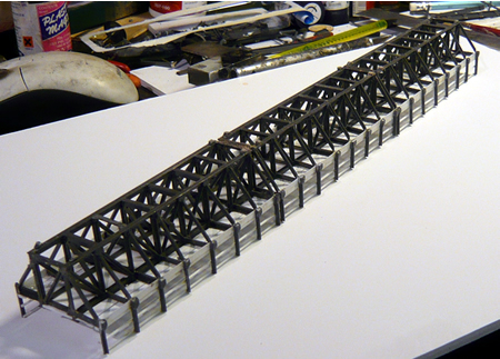
All the spans can be
glued together making sure they are straight and in line.
- click on image to enlarge
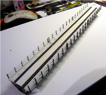
The deck is then added
and the 'timber' walk way planking
- click on image to
enlarge
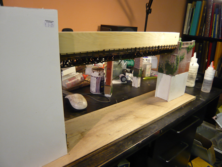
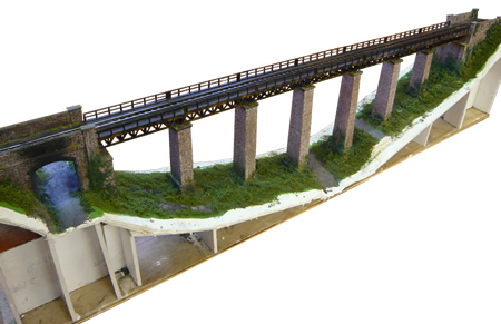
The viaduct is assembled on the plywood
base. Care must be taken to ensure the piers remain on centreline and are
vertical.
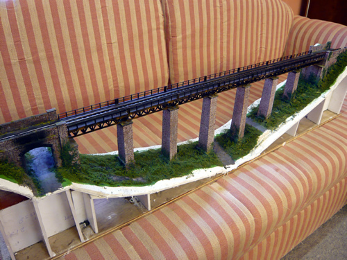
The 44" long, completed viaduct is now ready for installation. The road
and river bed can also be seen. The valley profile was built using foam
board covered in Modrock

|