|
laying the track
Early railways used chaired track. These
included the Festiniog, Penrhyn and Padarn Railway. Flat bottom rail
quickly became the norm for all subsequent lines.
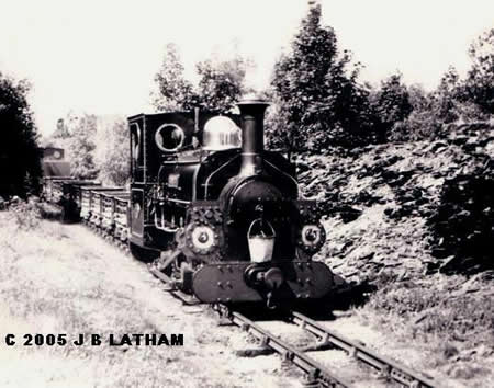
the Penrhyn Railway
Generally, narrow gauge track was quite
lightweight. The Lynton and Barnstaple Railway, for instance, was laid in
40 lb rail.
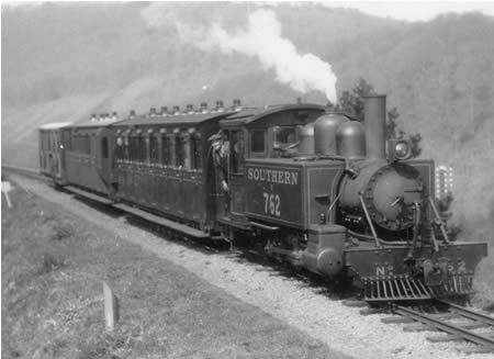
Lyn on the L&B
This meant that axle loads had to be
relatively light to prevent damage. Modern railways such as the new Welsh
Highland use rail almost double in weight. This can highlight the
narrowness of the track.
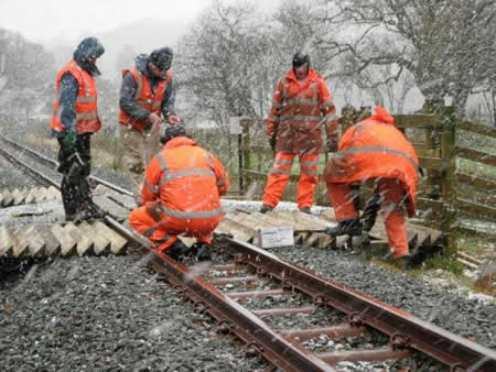
a cold day on the new WHR - photo by David
Firth
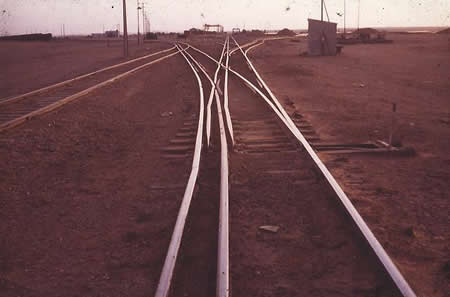
some railways have sections of dual gauge
track
These days, it is possible to hand build
accurate model track. Most of us still purchase ready made products.
hand built narrow gauge track by John
Clutterbuck
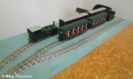
hand built 009 track by Lynne Grant -
photo Mick Thornton
The number one rule is to make absolutely
sure that your trackwork is as near to perfect as you can make it. Once
scenery has been added, it becomes very difficult indeed to put things
right. The next rule is to have curves as easy as you can possibly make
them and try to avoid double reverse curves.
Your locomotive may officially go round a 12"
radius point but will they do so smoothly without buffer or coupling lock
when pulling a train. If you ever intend to propel a train, the track has
to be even better. Always select live frog points.
Wherever possible, use transitional curves.
These are curves that gradually decrease in radius and you move towards
the curve apex.

The drawing above shows a transitional curve
(red) of track entering a spiral of fixed radius.
If you have used a track design software
programme, you will have the facility to print out the result full scale
and lay this down on your trackbed. This will make life a bit easier but in
the end, a good eye for setting down track is as good as anything. Often,
I will lay out track and lineside buildings on a wooden floor covered with
inexpensive brown paper from a roll used for masking off cars in paint shops and jiggle about with
them until I am happy with the result.
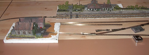
the start of laying
out of County Gate station
Once you are happy with the layout, you can
begin to transfer the information to the trackbed. I always suggest that
you select good quality 3 or 4mm ply for this purpose. This can be cut to
size and attached to the baseboard.
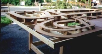
a complicated trackbed by
PLS baseboards
Model trains can climb gradients better than
the prototypes but I suggest that you keep the grades as gentle as
possible. If you are unsure, set up a section of track to your required
grade and try running a heavy train up it.
Some will require the track to be laid
slightly higher to represent modern trackbed. If this is required, you
will have to carefully cut an additional layer of thin ply which should be
firmly attached.
You may have to cut into the trackbed where
you have say, an inspection pit. It is best to complete and detail the pit
at this time.
track
You may decide to purchase ready made track
such as the products supplied by Peco or you may 'bite the bullet' and
build your own. A first class complete system for building your own track
is supplied by US company
Fast Tracks. Their website is first
class so it is really worth taking a look.
If using ready made track, choose the largest radius
points that you can fit into your plan. For 009, a new range called Peco
Mainline have points with an 18" radius. Their design is vastly
improved compared with previous 'Crazy Track' incarnations which I cannot recommend
being not very reliable and very rough running, apart from being only
12" radius.
Set track systems are also on sale. I suggest
that they are left in the nursery room where they belong.
Other points are available from manufacturers
such as Tillig.
Those who build their own track really do not need to
bother with the following section.
I tend to place pointwork in their
approximate position first and then lay track between. To cut track, use
either a Dremel cutoff disc and ensure that the end is smoothed to allow
the installation of a fishplate. I always start in areas where there are
points and add the long lengths of track afterwards. Keep the connected
track in smaller sections as it will have to be handled. Do not forget to
ensure that parallel tracks afford sufficient clearance for trains. I have
once forgotten about duckouts on brake coaches!
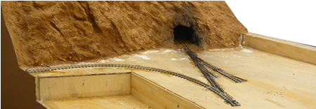
the start of track laying
Gradually, you will be able to connect the
track together as you require. Once happy with the result, the next job is
to solder the rail joints, an essential step to ensure good continuity. Do
not forget to use insulating fishplates at point frogs. You may consider
building in the break a little further away from the frog. This could very
well prevent collisions if you are using DCC.
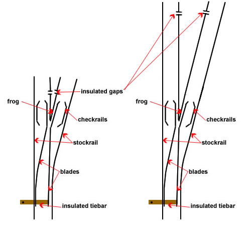
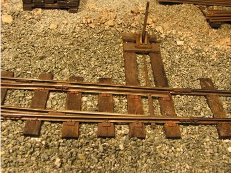
preferred remote insulated rail joints
shown on the right image
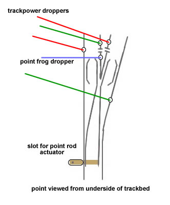
Once you have connected and soldered your
track section, it is time to add wiring. Carefully turn over your section
of track. The point frog will have to change polarity when the point
switches so it will require its own power supply which will be connected
to a bipole switch. I always use thin white wire for this application. Use
a short length, say 12" and solder one end to the underside of the frog.
You will also have to lead power to the main running rails at regular
intervals of about 24". Again, always make sure that you use two colours,
say red and green, and do not mix up polarities. I
always use red wire for the rail next to the backdrop and green towards
the front of the layout. Again, solder lengths to the underside of the
rails.
Once complete, turn the track over again and
place it in the correct position and mark the plywood where the wire
droppers are located. Push the track over to one side and drill the
plywood trackbed with a small clearance hole to accommodate the wires.
Feed the wires through the holes and check that the track is in the
correct position. There have been times when I have had to redrill holes
until I am satisfied with positioning. Hold the track section down in its
correct position with Gaffer tape and using a propelling pencil, place it
through the tiebar actuating hole and operate the point side to side.
This will leave a line which must now be
opened with a small drill into a slot. Make the slot a tad longer at each
end to avoid binding.
Once you have completed the section with
points, you can now attach it to the baseboard. Mix up some 20 minute
epoxy and place blobs at the end of sufficient sleepers to firmly attach
the track. Make sure that the sleepers either side of the point tie bars
are very firmly fixed indeed.
As the glue begins to thicken, this is the
time for any last minute positioning adjustments. Eye the track at low
level down the rail and you will easily see any wobbles which can easily
be removed.
I always make sure that the track is
completely flat onto the trackbed by placing a small sheet of MDF (as flat
as you will get) onto the track and weighting it down until the glue has
cured. Ensure that no glue has migrated onto the tiebar. This can be
cleared off if necessary if the glue is still slightly soft.
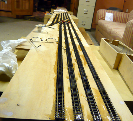
tracklaying on the fiddle yard
You can now attach the flexitrack remembering
to include track power droppers. If you require a block section for any
reason, do not forget that they should have their own power feeds. Use
different colours of wire. Most block sections only require one rail to be
isolated. Where track is to pass from one baseboard to the next, terminate
the track about three inches from the end.
Fill the gaps between insulated rail gaps
with a little epoxy. This will prevent rail movement and shorting in hot
weather.
Model rail will expand and contract just like
the real thing. Once you have laid all of the track, it is really worth
while heat soaking it. I just bang on a couple of fan heaters until the
room is unbearable and leave for an hour. You may find you get local
problems that will have to be rectified. Some exhibition halls can become
unbearably hot and you really do not want to find such problems in these
circumstances. When the layout, on the other hand has become extremely
cold, some joints may also fracture. This is of course much harder to
check for.
Where track goes from one baseboard to the
next, fit the baseboards
together and we lay track across the joint. Leave an expansion gap or
0.5mm when joining to the laid track and do not solder the fishplates
here. You will therefore have to provide this short section with its own
track power feeds for reliability's sake.
The final track section should be set in
solid epoxy glue to prevent any movement at all. Some chose to solder the
rail ends to pins or copper clad as well. Once the glue has cured, you can
cut the track at the baseboard joint with a fine saw.
The most important issue is to ensure that
the track is as near as possible at right angles to the baseboard joins.
Oblique angles will cause nothing but problems. You may have to modify the
baseboards so that the joint is actually at right angles.
It is now the time to install any working
signals. These will have motor actuation from below. Although expensive, I
use signals provided by Model Signal Engineering (Wizard Models) along
with their 'bouncy' actuators.
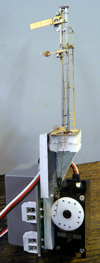
after painting, this signal is ready for
installation

|