|
A simple method to make class 08 steam chassis
A new series of
Glenthorne locomotives have been described here using heavily modified
Bachmann 08 diesel chassis. Finally it was possible to build 8 coupled
locomotives but such work requires the complete dismantling of the
chassis which is extremely hard to get back to work well.
I was asked to develop the most simple
way to add valve gear to such a chassis.
I now always use ROCO valve gear which
can be ordered from Gaugemaster. There are two types.
- Roco 122875 from model HOe OBB 399.
This has two slidebars
- Roco 116295 which has a single
slide bar.
Parts are NOT interchangeable.
The first example uses
Roco 122875. The connecting rod may be attached to either the rear wheel
set or the centre one (preferable as this is the driven set). In this
case the rear driver was chosen as I wish to build a shorter locomotive
more suitable for Cliffhanger. If the centre driver is to be used, the
outer chassis frame will need to be extended using thick Plasticard.
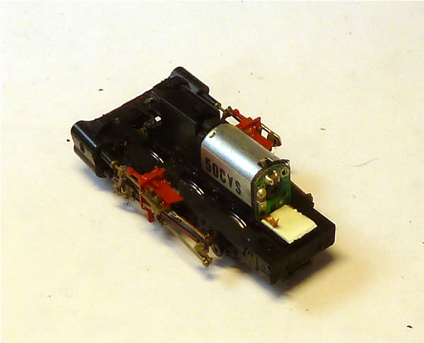
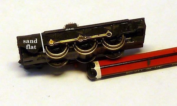
Remove the body of the
locomotive and sand flat the frames just forward of the front spring
hanger.
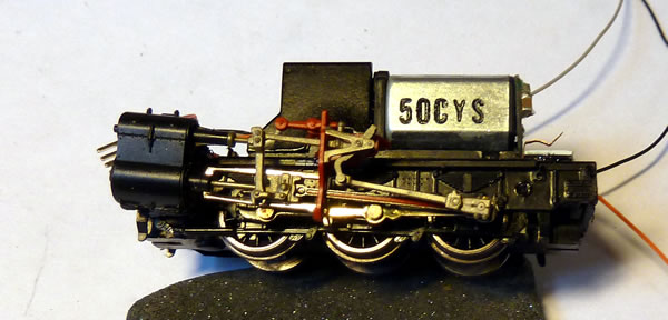
The motor can be removed by prizing open
one of the locking tabs using a pointed blade from below. It is not
necessary to remove the brake rigging although the photo above shows
them missing. The four small holes previously used for attaching the
body should be drilled out to give clearance for 12 BA screws.
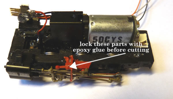
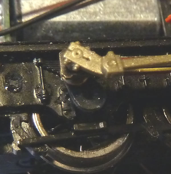
The valve gear needs to be divided into two
sections. For this, it is important to lock all the parts of the gear
together with epoxy glue as shown here. I also drop a small amount of
thick superglue to lock the slidebars into the support. They come as
push fit only.
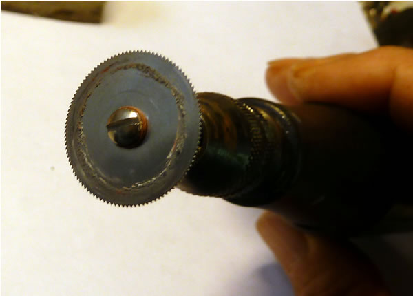
Cut the red slide bar support as shown in
photo. I use a fine toothed cutting disc for this.
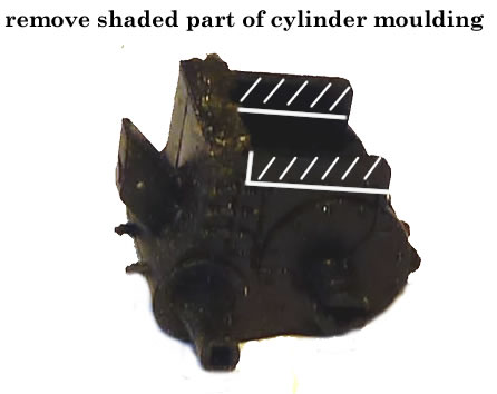
Also cut back the rear of the two cylinder
blocks.
The cranks which will receive the
connecting rods and eccentric cranks need to be opened up so the cranks
will push fit into them.
Scrape off the paint on the coupling rods
and pins and remove the pins where the connecting rod is to be fitted.
Fit the connecting rod on one side using
the return crank. The spigot is delicate and easily broken. Ensure the
hole is large enough to allow an easy push fit. Cut the spigot flush at
the back of the crank.
Now glue the cylinder in the required
position making sure that there is full movement of the crosshead and
the the return crank. The cylinder may be attached level or angled
'according to taste'. Ensure that there are no binds or contact points
while the glue dries. Repeat for the other side. You should now have a
free running perfect chassis. Attach the return cranks with thick
superglue from the rear and glue the slide bar supports to the chassis
with epoxy.
If you are using DCC, remove the spigot on
the chassis which hold the phosphor bronze tag onto the motor and then
replace the motor and check for operation.

|