|
Building the Glenthorne Harbour
Baldwin No2
As the harbour traffic increased, it became
clear that more powerful motive power was needed. In 1906, they purchased
from Baldwin, USA, at very good terms, a 2-6-2 tender locomotive which became the only locomotive
to carry a name; 'Ben Halliday' ..............
This project began when Victors Scale Models announced their intention to release an etched
brass kit for Sandy River and Rangeley Lakes Baldwin No 19. The principle
data is written below.
The kit was dispatched 9th Dec 2008 and
arrived two days later. Sadly, Victors are no more but one hopes that the
kits will be re-introduced.
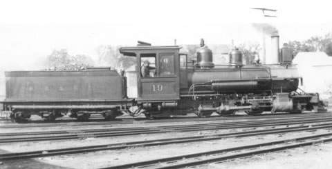
Built: 1904
Cylinders: 12" x 16"
Driving wheels: 33"
Total weight: 50,000lbs
Tractive force: 10,682lbs
Tank capacity: 1,500 gallons
Formerly: No.8 of the SRRR
Scrapped: 1935
Instructions for the build of this loco can
be downloaded as PDF files here
photos,
text
motor installation
The first part of this odyssey uses the
photographs supplied in the PDF files as Jenny was on a cruise and
had the camera. The kit arrives in a nice deep plastic box which serves
well to keep all the little bits in during construction. At £160, the kit
is quite expensive (double that of my Backwoods jobs) so it does have to
be good. The first dilemma was whether to out shop the chassis or not. I
have failed with Backwoods and always out shop their chassis but I have successfully
scratch built chassis in the past. I figured that I had to be able to
build this one myself. If successful, the kit is actually cheaper for me
than a Backwoods one. If I mess it up, it represents quite a loss!
The supplied instructions are a bit
deficient. For instance, the frets contain many tiny parts. There is an
image of the frets but there is no numbering and a key to identify all of
the bits.....and there are an awful lot of them. The written instructions
are 'terse' to say the least and frankly do not explain sufficiently well
for a beginner to tackle the job.
For starters, it would have been nice to have
a list of the tools required.
I used 2 soldering irons, (medium and small).
Baker fluid flux and normal and low melting point solder.
10BA and 12BA taps
wheel press
quartering jig is preferable
selection of small screwdrivers and files
Dremel tool
back to back jig for N gauge
The design of the chassis is as things ought
to be. The is an inner chassis where the wheels are retained by a keeper
plate while the outside frames are slotted.
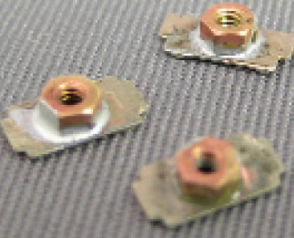
The first job was to remove the inner chassis
and fold it up. There are several places where small nuts have to be
soldered onto the frets. The trick to avoid having solder run into the
threads is to shove a cocktail stick into the hole and then it works fine.
Pity they did not mention this. I still do run a tap through captive nuts
to make assembly easier later.
The chassis should be soldered up on a sheet
of glass to ensure that it remains really flat. Once sure that the chassis
is properly square, I also ran fillets of solder along the fold lines.
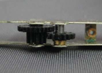
Almost straight away, you will be fitting the
drive train. There are two identical gears. One has a clearance fit for
the shaft while the other has a push fit. Make sure that the clearance fit
gear is used. The gear train is fitted as shown. The gears are designed
to rotate on the shafts while the shafts are held captive.
Prior to
installation, I tinned one end of each shaft and left a small blob of
solder there (here I used low temp solder). Once together I touched the
solder blob with a soldering iron fusing the shaft with the chassis. Great care is needed to
prevent over heating the gears. I always use plumbers flux which in my
mind gets things going with the minimum of heat. No instructions how to
fasten the shafts are given. Be sure to carefully wash the gear train with
hot water and detergent to remove the flux as soon as possible to prevent
any corrosion of the steel shafts. Drop a spot of oil into the gear
bearing surfaces.
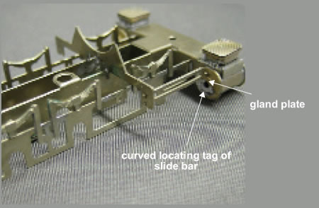
From then on, construction for a while
is straight forward. The brass castings are good quality but care is needed
to clean the cylinder blocks. The slide bars have a locating tag which
wraps around the gland plate. Make sure that the casting is properly
cleaned up here otherwise it will not fit. At
this stage, do not solder the slide bars onto the boiler support.
Quite quickly you will be beginning to have a
good looking chassis. The detail is really excellent by the way. The
equalising bars for the rear pony truck need to be cranked outward to give
sufficient pony truck movement. The instructions show two wires passing
across the chassis to fit them. Once soldered up, cut the wires out as
they will foul the rear truck.
Once you
have prepared the keeper plate you will find yourself fitting the wheels. The instructions suggest that 2 BA nuts are
soldered to it. This is where there is an error as the keeper plate
extends over the hole that will eventually house the front body securing
screw. It is better to shorten the keeper plate so that this important
screw is exposed. This means that the front pony truck needs to have its
length extended so that it attaches to the front keeper plate screw. At
this time it is good to solder the double washers over the end holes as
shown. These retain the pony truck arms while still allowing the screws to
be tightened. By the way, make sure that the small tags on the keeper
plate properly locate in the slots provided. Adjust them if necessary.
The 12 BA screws are all supplied long and
you will have to cut them down. Always run up a nut first and then cut and
clean up the end. Once you remove the nut, working it a little at the cut,
the thread will work.
The top hat bearings are seriously
engineered. The instructions do not tell you to
shorten a pair to allow for installation of the drive gear. IF YOU DO NOT
DO THIS, BUY TT TRACK! First, attach the gear onto one axle,
accurately central, locking it in place with Loctite 603.
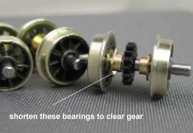
The bearings need to have a flat sanded on
them and this is used to retain the bearings under the keeper plate. The wheels are simply pressed on making sure
that all of the bearings are fitted the right way round. Make sure that
the axles extend equally both sides and that the correct back to back
measurement is maintained.
If you have a quartering jig, fit the cranks
at this time. The 14BA screws are held in place with Loctite 603. While scale cranks are supplied in the etch,
Victors also supply push on plastic ones for idiots like me.
The
wheels then happily drop into the chassis (make sure that the bearings are
all of the way up the slot) and the keeper plate installed. The gear train
and wheels should turn freely and mine did first time.
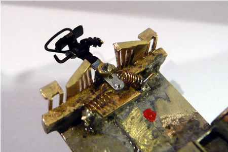
Again, omitted from the instructions is the
explanation of the electrical pickup. For Lord's
sake get all the wheels fitted the right way round. Otherwise
the dead short will be very disheartening when you put it on the track.
Confirm each time which are insulated wheels. I painted a red spot on the
live side to remind me.
The body and chassis is live and the tender
will be the opposite polarity so the link must be insulated and the tender
and locomotive must never touch! I chose to modify
this arrangement and the pillars supporting the bogies were built in solid
plastic. The bogies rub on an 8 BA washer and a thin wire is soldered to
this and lead to the cab. I found this a far better arrangement than the
suggested method and obtained more reliable electrical pickup.
Check that the wheels all touch the glass
plate. If any distortion has happened, a small twist of the chassis is all
that is needed to adjust things correctly.
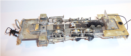
I did find that although the chassis sits flat on a sheet of glass, it is
a bit too flexible and could easily go out of kilter. I soldered in an
additional cross member once the outer frames and wheels were fitted which
had made the chassis far more rigid. One can also see how the rear pony
truck beams have been cranked out to allow for sufficient pony truck
movement.
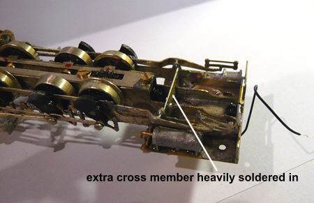
click on image to enlarge
If you do not have a quartering jig, the cranks are then added on one side. These
can be attached using epoxy or Loctite. The right hand cranks lead. Once
the glue has hardened it is time to add the other cranks and quarter. This
can be done by eye, using Loctite which
takes some hours to go off: 20 minute epoxy would work too. The connecting
rods need to have the holes opened out a tad, and I very slightly
slotted the holes except those on the drive axle which I left an accurate
fit. These should be temporarily fitted, being attached by a 14BA nut on
the centre driver. Check that you have the cranks properly quartered
before the crank attaching glue goes off!
The forward pins have to be cut back to clear the
slide bars. After about ten minutes of jigging the arrangement around, I
succeeded in getting the quartering right and the chassis move backward
and forwards without binding. One then leaves it a while to allow the glue
to go
off.
The forward and rear rods are attached by
soldering a washer onto the pin. Put a thin piece of paper between the rod
and the washer to prevent soldering the lot solid. I always hold the
chassis upright when soldering here which reduces the risk of solder
seeping down onto the rod. At this time leave the centre bolt as is and
remove the temporary retaining nuts.
I then installed
the motor. As the kit stands, the motor is a bit offset to the gear. I
slotted the bracket so the the worm gear was aligned directly over the
gear. After checking the mesh...gears should never bottom out, the chassis
was run for four hours each direction. Check that the motor does not over
heat at regular intervals. Perfect running straight off! Hey! I can build
this!
One error and a crankpin might have to be replaced. I would have liked to
see a couple of spares included.
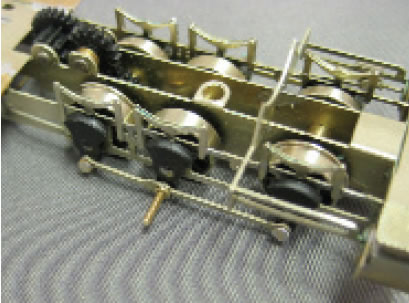
The crosshead is riveted onto the connecting
rod and assembled. The last washers finish the job. Finally, the slide
bars are soldered onto the boiler support.
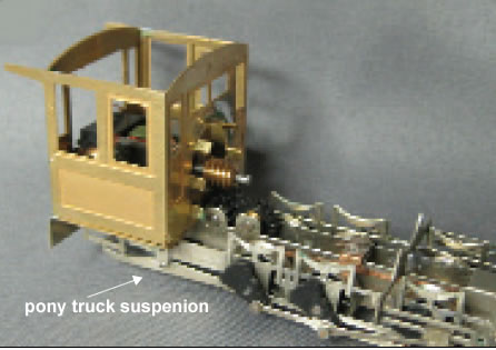
the coupling arrangement - click on image
to enlarge
The next job is to fold up the cab. This is
not as easy as it should be as the fold line is not sufficiently etched.
The real fun starts with fastening the boiler
wrapping around a brass tube. Firstly, I annealed the sheet with a blow
torch and gradually bent the sheet around, soldering as I went. The job is
a little difficult but the end result was just fine.
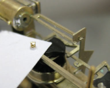
this shows my alternate way of fixing the front of the body - I can get
away with this solution as my loco is freelance! -click on image to
enlarge
Now, talking about modifications, our loco is
representing a Baldwin delivered to the Glenthorne Harbour Authority which
is an awful long way away from Maine! In Devon they do not even put bells
around cows so why should steam engines have them. The 'Casey Jones' oil
lamps are also a casualty. These have been replaced by more modern
electric lamps and a steam generator. These are fitted with LEDs and will
be directionally operated by DCC. I cannot find the safety valves
either...ours are being fitted on top of the dome and of course we are
fitting a proper whistle.
The sandpot will also be installed with
sandpipes and an operating lever running to the cab. I am sorry, Victors,
I am incapable of building a kit without modifying it, even if a gun was
put to my head!
Now I do understand why Victors produce this
kit in HO scale, but we are 4mm scale, so a few changes have been made.
The holes in the boiler wrapping etch to take the footplate brackets were
filled with solder and new holes drilled 1.5mm lower....it is just that
our 4mm/ft guy are that much taller! To fit the footplates, I used an old
US modellers trick of passing .75mm rod right through the boiler and
soldering the footplate onto these. It is far easier to get things level
and a lot more robust. The rod will be shaped later. The rods were set
into the boiler with epoxy.
Well, we know that the instructions need to
be reworked. In the meantime, the pony trucks are fabricated from the
nickel silver parts which have a long slot. The end tab folds over to trap
the wheelset. The pony wheel sets also have one live wheel so for heavens
sake fit it the right way round. Remember to extend the front pony track
arm if you have modified the keeper plate.
The rear pony truck has this outer fret that
has been fitted. This needs to be cranked outwards otherwise there will be
no room for the truck to swing. I painted the inside of these with epoxy
to prevent shorting. The wheelsets have a small part of the axle
protruding and this should be removed. I added additional lead weight to
the pony truck.
CAUTION
The back to back
measurements of the small wheelsets are incorrect and need resetting.
The electrical pickup bears as it should do
on the back of the driving wheel sets. The clearances are very small and
it would be only too easy to get a direct short onto the chassis. I glued
a very thin strip of plastic strip onto the chassis to prevent this
happening.
The tender was harder than I thought. The
outer wrapping should be annealed with a blowtorch to make the bending
easier. It is still quite a challenge to get right. I did not bother
to have the tender body separately screwed to the base but soldered the
whole lot up together, leaving a largish access hole into the tender
cavity. I chose to incorporate a few dents in the tender.
If built to the instructions, the link to the tender must be insulated and
the tender is of opposite polarity. Remember all of the wheels pick
up on one side unless you opt to incorporate the modification
previously described.
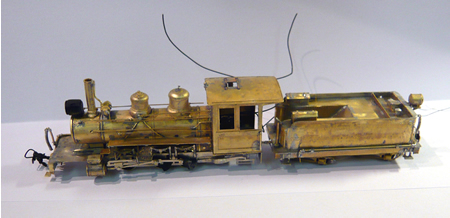
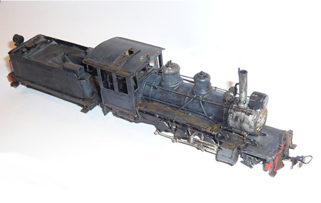
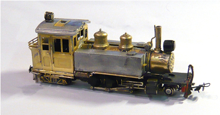
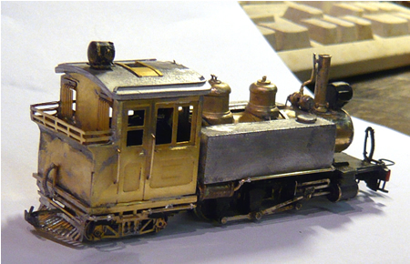
the 'British version' close to completion (pony trucks not fitted here) -
click on image to enlarge
Having fed the light wires through it, I
filled the boiler with lead shot mixed with epoxy. The tender was also
weighted as it was far too light.
So it is now going to be run for quite a few
hours (it is still DC) until is is really run it. It works, does not
waddle and has good slow speed characteristics which will improve with
running. However, after 8 hours running I noticed
that the bearings had slightly worn the retaining slots and had begun to
move around slightly. Knowing that all was well with the
alignment, I degreased the chassis and fastened the bearings onto the
inner chassis with 5 minute epoxy, taking real care to make sure that none
of it involved the drive gear on the rear axle. The glue could be easily
removed if necessary but it firmly retains the main bearings in the slots.
In all, the chassis has logged 12 hours
running without further problems showing up.
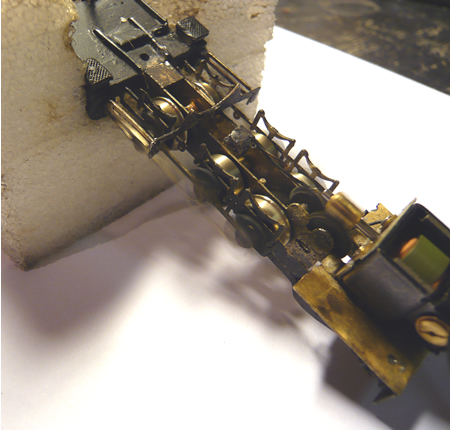
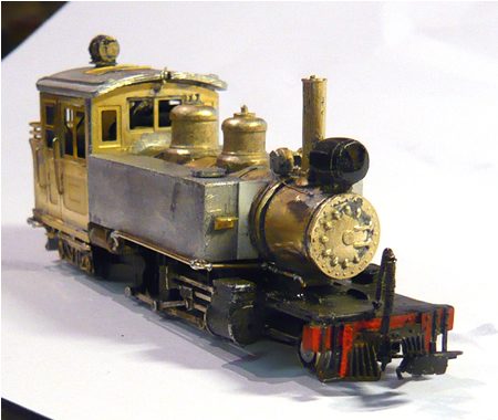
running in - click on image to enlarge
all that is left to do is the chipping, GHR decals and name/number plates
- click on image to enlarge
After painting and my usual weathering, the
glazing was installed. This was given a wash of thinned black to simulate
dirty glass which will hide the motor somewhat. I also painted the
armature of the motor black.
At which point, Whinge jumped on the work bench and dislodged the chassis
where is was running. This jammed the flywheel and the motor burnt out
..... thanks Whinge ...no turkey for Christmas!
I am also concerned with the very fine
flanges on the bogie and pony wheels for running on Peco track. This model
was designed for the US market. The wheels have now been replaced with
similar size but with 009 Peco profiles.
I have had similar problems with Backwoods
pony wheels and have always replaced them. I am hoping that a different
wheel profile is available when ordering the kit. There is a country mile
of differences between test tracks and real layouts and the derail rate is
too high to be acceptable. I tried the model with alternate pony trucks
and it works fine. The wheels that come with Greenmax bogies are perfect
for the job as they have the correct profile and are grounded on one side.
They are supplied by Wellington models.
The next problem is that the traction of the
engine is very low. It is just too light to haul heavier 009 loads,
despite having been stuffed with lead wherever possible. Below is a photo
of the amount of extra weight needed to make the loco as heavy as our
'Lyn'. 3 large sheets of lead and 10 into 2 does not go! With this
ballast, the loco works perfectly. I have to say that all County Gate
stock is heavily ballasted including rolling stock and of course we have
some quite stiff grades.
The most sensible solution for me was to
convert the loco into a tank engine so that a lot of additional ballast
can be added.
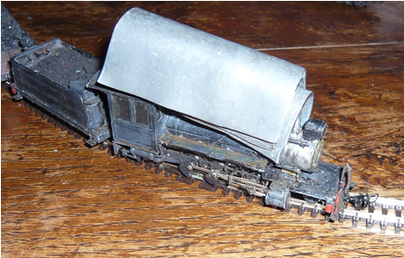

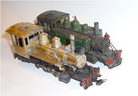
No 19 alongside Lyn (that has solid lead tanks) very
similar in size and easy to convert - click on image to enlarge
butchery
I had not looked at a Langley 'Lyn' body kit
before. The brass frets go together very well but the one piece casting of
boiler and tanks left quite a lot to be desired, with some distortion and
flash that obscured some rivet detail. The tanks were cut away from the
boiler and the assembly went together in two days. There is now sufficient
weight for the engine to perform extremely well. A Langley bogie from a
wagon kit was modified as the rear 4 wheel truck.
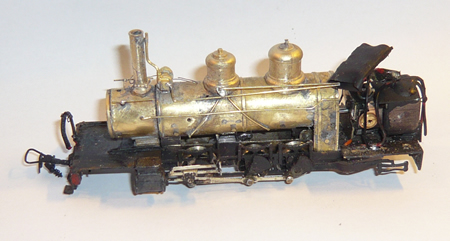
ready for the paint shop - click on image
to enlarge
click on image to enlarge
click on image to enlarge
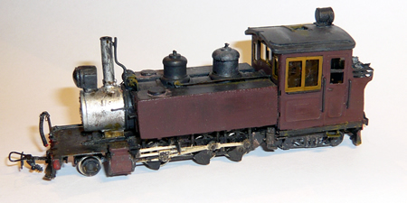
painted and awaiting lining and decals - click on image to enlarge
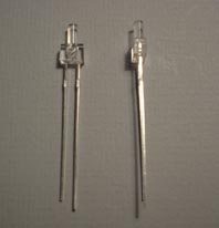
We used warm yellow 'lighthouse' LEDs
supplied by
Express Models . The body of the light is quite large although the
bulb is only 2mm in diameter. The bodies were 'lost' in the smokebox and
bunker. A resistor must also be fitted to bring the voltage down to that
required. I have to say that the yellow light looks so much better than
the ghostly blue tinted normal white LEDs. I simply set the LED in epoxy
and form a lens with a drop.
LEDs only work with the current running one
way. It is important to ensure that you wire them both the right way
round, otherwise your loco will remain 'dark'. The Digitrax DZ 125 chip is
used.

|