|
Lynton and Barnstaple model
signalling
by Bob Barnard
ed note: Bob is a professional
signalling engineer and his work in this field is seminal. It also shows
what happens when you bring your work home!
The definitive description of the signalling arrangements on the original
L&B line is given at:
http://www.trainweb.org/railwest/lbrsignals.html
There are still many unknowns about details of the original signalling,
and the operation of the line, but this website includes what is probably
the best information available to date, and is updated if new information
comes to light.
|
Technical Standards for Model L&B Signalling |
Although my L&B model is an attempt to recreate the original line in
009 scale, in order to be able to operate it in a manner equivalent to the
original line, there are some areas where alternative signalling standards
have been devised, in order to overcome the practical constraints of a
small-scale model. Obvious differences from the original signalling
include:
• There is no need for telephones to allow operators at different stations
to converse, as the layout is housed in one room
• It is not practical to carry physical tablets on 009 trains (4mm scale
working tablet instruments would be a step too far!)
• Lever frames need to be large enough to suit 12”/1 foot scale fingers
• It may be necessary to operate stations from either side, especially at
exhibitions
• Facing point locks are not really required on a model, especially as
those on the L&B were “economical”, i.e. they did not involve the use of
separate levers
• L&B level crossings were released from the
nearest signal box, and operated locally by hand. This may not be ideal in
a model situation.
I wanted some system to replace the tablet instruments for single line
sections. On some secondary routes around the world, so-called “Tokenless
Block” systems are used to release the signals controlling entry to single
line sections, and this seemed like an ideal solution for my model.
Therefore, I developed a Tokenless Block System (TBS) based on BR
practice. In order for this to operate, it needs to be interlocked with
the starting signals at passing loops, which the Tyers instruments on the
original line were not. However, this seemed to be a sensible compromise.
Surprisingly, in view of its suitability, I am not aware of tokenless
block having been used by other modellers.
Many model layouts these days use oversize but realistic-looking lever
frames to control points and signals. This provides a satisfyingly
authentic method of operation. A few of these models also have working
mechanical interlocking between the levers. With very simple track
layouts, I decided that my long-term aim should be to provide full
mechanical interlocking.
It is possible to build-in the lever frames into the station layouts, and
operate points and signals mechanically by rodding under the baseboards.
However, this effectively prevents operation of the station from the rear
side. The alternative is to build a separate “signal box” unit, and
operate points and signals electrically. I have used both approaches in my
L&B models.
A set of common engineering standards has evolved as I have built my
models, so that spares can be used at any station. These standards include
power supply arrangements, block circuits and electrical drive
arrangements for points, signals and level crossings.
A number of interim signalling arrangements have been implemented on the
model, in the interests of saving time, but it is intended that these will
eventually be brought up to the general standard.
The following sections include more detailed descriptions of the common
subsystems.
A standardised form of Tokenless Block
control is used for each single line section, using one circuit in each
direction in a lineside cable route, and providing facilities for
acceptance of trains and release of signals. The tokenless block system
also provides block bell communication between stations.
The Tokenless Block System is a method of controlling single line sections
without the use of physical tokens. It is derived from British Railways
Tokenless Block systems, and is intended for implementation on model
railways.
In order to clear the starting signal for a train to proceed into the
single line section, it is necessary for the signalmen at the two ends of
the section to establish, by the correct sequence of operations, that the
line is clear. The signalmen can then set the block section for the
appropriate direction, and the appropriate starting and home signals can
be cleared according to normal block working methods. When the train
arrives complete at the other end of the section, that signalman
normalises the block once again, ready for another train.
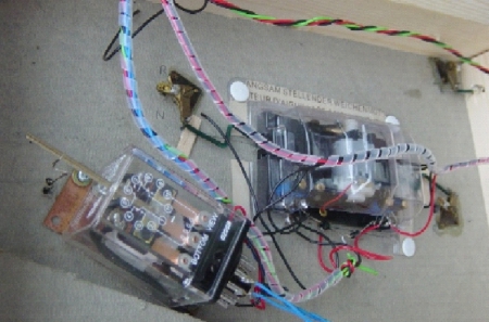
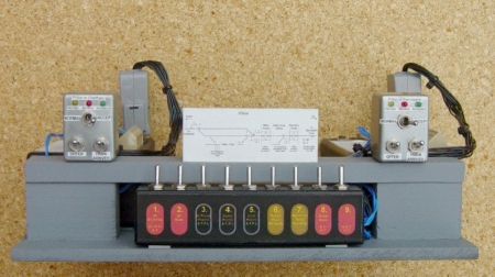
At each end of the section, there is a block instrument and a relay set.
The relay set contains 4 relays and is fed from a local 15 Volt a.c. power
supply, and requires contact inputs indicating the status of the home and
starter signals at the station. It provides 12 Volt d.c. outputs to the
home and starter signal lever locks.
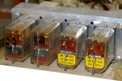
Tokenless Block instrument (l) and Relay Set (r)
The circuit between the relay units at the
two ends of the block section consists of two conductors and a common
return path.
The system is designed for use with semaphore signals with electric lever
locks. Additional circuits can be added to interface to colour light
signals.
The normal sequence of operation for the section between A and B is as
follows:
• After the passage of a train and the normalisation of the block, each
signalman sets his block instrument to “Accept”, provided no shunting is
taking place into the block section. The block status is indicated to both
signalmen as “Normal” (Yellow)
• When the next train arrives (say) at A, the A signalman sets his block
instrument to “Normal”. He then presses “Offer”
• At B, automatic acceptance of the train
occurs, and the block status is indicated as “Blocked” (Red). If the B
instrument were not set to “Accept”, this would not occur, and an audible
warning would be given
• When acceptance has occurred, the block status at A is indicated as
“Accepted” (Green)
• The A signalman may now, at any time, release his starting signal
towards B, using the economiser button to energise the signal lever lock
as he pulls the lever. As the signal clears, the block status changes to
“Blocked” (Red). If he replaces the starting signal to danger, he cannot
then clear it again. This prevents a second train being accidentally
signalled into the section.
• The B signalman can now, at any time, clear his home signal from the
direction of A, using the economiser button as he pulls the lever. If he
changes his mind about the route for the train, he can replace his home
signal to danger, move the points, and then clear it (or any other
appropriate home signal) again
• The A signalman replaces his starting signal to danger once the train
has departed from A
• The B signalman replaces his home signal to danger once the train has
arrived at B
• The B signalman checks that the train has arrived complete at B (tail
lamp) and then sets his block instrument to “Normal”, and presses “Train
Arrived”. The block section status is then restored to “Normal” and
indicated to both signalmen by “Normal” (yellow) indications
• Each signalman then sets his block instrument to “Accept” again,
provided no shunting is taking place into the block section. The block
status is indicated to both signalmen as “Normal” (Yellow).
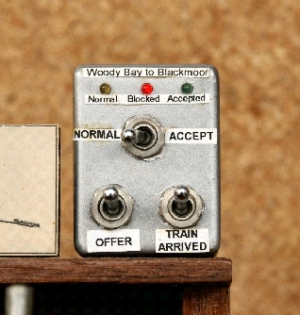
The Block Instruments are located on
(non-prototypical) block shelves over the lever frame at each station. Two
different designs of relay set are used, but all units have standard
connectors for the block circuit, allowing any two stations to be linked.
The two instruments at a passing loop can also be linked to one another
for testing. The appearance of the block instruments is very 1960s, with
grey boxes and labels against each indication or switch.
This tokenless block system works extremely well, and again gives an
authentic feel to operation of the model, even though it is quite
different to the original Tyers tablet system used on the L&B.
Lever frames, with mechanical interlocking between levers, are (or will
be) provided at all stations and passing loops.
Home and starting signal levers are released, when permitted by the
Tokenless Block system, via 12 Volt d.c. solenoid lever locks fitted with
economiser buttons. Signal clearance is dependent on local detection of
electrically operated points and level crossings, and of slots from
adjacent signal boxes.
Two alternative approaches to point and signal control are adopted:
• The lever frame, interlocking and block shelf may be located at the
station itself. In this case, station area points and signals are operated
directly from the lever frame via rodding, and detection is provided
purely according to lever position.
• The lever frame, interlocking and block shelf may be remotely located
(or portable, for ease of maintenance), and connected to the station by
multicore cabling (D-type computer cables, 9 way and 25 way). This
approach means that a non-interlocked switch panel may be used as an
interim solution, in place of a fully interlocked lever frame.
In the case of electrical operation, the lever frame (or switch panel)
provides feeds as follows:
• 12 Volt d.c. feed, switched in polarity by the lever, is used to feed
each electric motor (slow-acting) point machine. Electrical point
detection is provided, with a correspondence circuit used to release a
lever lock to allow the controlling lever to reach the fully normal or
reverse position.
• 12 Volt d.c. feed, switched in polarity by the lever, is used to feed
each semaphore signal via local point detection contact(s). Signals may
therefore, in principle, be operated by several different types of
mechanism:
o
12 Volt d.c. relay mechanisms, via a diode
o
12 Volt d.c. motor mechanisms (e.g. slow-acting point machines)
o
Memory wire mechanisms, via a diode (tried but not used)
o
Direct operation of bi-colour LED colour light signals (not used)
In all cases, electrical "Signal On" detection is provided at the signal,
either by detection switches or by contacts of the operating relay
mechanism
• 12 Volt d.c. feed, switched in polarity by the lever, is used to release
each level crossing.
Unlocked mechanical ground frames are provided at in-section sidings.
It would be possible to prove ground frame levers normal by means of
contacts in the TBS line circuits. This would prevent the section being
cleared with a ground frame incorrectly set, neatly replicating the
prototypical feature whereby the block cannot be released if the ground
frame is left unlocked.
The current standard mechanism for operating signals is a Maplin 12 Volt
d.c. power relay. These are modified as follows:
• Bend the contacts apart slightly, to increase the travel of the armature
• Attach an arm made from a piece of Code 100 rail to the armature, to
extend the travel
• Drill a large hole in the plastic cover for the arm to pass through
• Attach a mounting plate to the cover, for screwing to the baseboard.
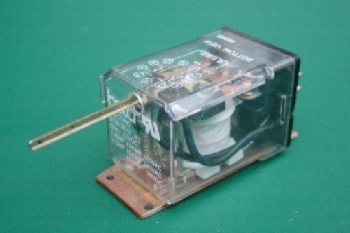
Relay signal mechanism
Interlocked points (e.g. loop and siding entry points) are operated by one
of two means:
• Directly by robust mechanical rodding from the lever frame
• Electrically by 12 Volt d.c. slow-acting electric machines (either
Fulgurex or Lemaco).
In either case, the drive is taken by plastic covered galvanised garden
wire to a substantial brass crank fixed under the points, where the throw
is reduced to about half. A long steel pin in the shorter arm of the crank
projects through a slot in the baseboard and passes through a hole in the
fibreglass tiebar linking the point blades. A “joggle” is incorporated in
the garden wire, to allow small adjustments to be made in situ with
pliers.
Point machines use a standard 12 Volt d.c. 3-wire drive and correspondence
circuit, with wiring details defined for each type of point machine.
Point machines are fitted with 3 pairs of detection contacts (Normal/Not
Normal and Reverse/Not Reverse), which are used as follows:
1 pair for motor current cut-off and correspondence circuit
1 pair for traction current switching
1 pair for detection in signal circuits
No facing point locks are provided.
It would theoretically be possible in future to use electronic presence
detectors to replicate the operation of the economical FPLs.
A signal relay mechanism (l) and point machine (r) installed under a
baseboard. The point machine drives the loop points and trap points, via
the cranks at either end of the mechanism
Yard points are unlocked, and are individually operated by local switches
via robust rodding. No detection of such points is needed in signal
circuits, and the switch contacts control traction current.
Level crossings are released by a 12 Volt d.c. feed, switched in polarity,
from the lever in the controlling signal box.
Level crossing gates are operated by a 12 Volt d.c. electric motor, via a
mechanism that sequences the gates. The mechanism includes a
correspondence circuit operating the lever lock, to prevent the
controlling lever completing its movement until the gates have been
operated and detection switches have proved the crossing gates closed to
road traffic.
Local switch panels are provided near each crossing. These switch panels
provide two modes of operation:
• In “Local” mode, the release from the signal box is indicated to the
local operator by a “Open” (Green) indication, and replacement of the
crossing lever in the lever frame by a “Close” (Red) indication. When an
indication is present, the local operator may, in his own time, operate
the gates using the “Operate/Halt” switch on the local control panel.
• In “Remote” mode, release of the gates by the signalman causes them to
open, and replacement of the lever causes them to close. Operation of the
“Operate/Halt” switch on the local control panel stops the gates moving
immediately, in the case of an obstruction or fault.
Each crossing is detected closed to road traffic in the circuits releasing
signals reading over that crossing.
All signalling is fed from a nominal 15 Volt a.c. power supply provided at
each station. This supply is used directly by the tokenless block system,
and is rectified and smoothed for use by the point machines and lever
locks. Signalling power is normally fed from separate transformers from
the traction power, to prevent momentary loss of signalling power during
traction short circuits following derailments. However, the choice of 15
Volt a.c. means that, for testing purposes and for exhibitions, traction
power and signalling power can be derived from a single controller.
|
Provision for Degraded Modes of Operation |
It is very desirable to be able to continue to operate traffic following
failures of the signalling system. The design philosophy addresses this
issue by means of the following measures:
• Mechanical interlocking and rodding to points and signals, once
adjusted, is regarded as inherently simple and reliable, and no special
provisions are made to work around failures of such elements. “Joggles”
are incorporated in rodding, to permit simple adjustment in situ.
• Electrical operation of points and signals is more prone to failures,
mainly of electrical connections or of the adjustment of sensitive and
inaccessible detection switches on the lever frame. Interim switch panels
used prior to completion of fully interlocked lever frames are therefore
retained for test purposes and for emergency use whilst lever frame faults
are repaired.
• Failures of the block system can prevent the release of electric lever
locks, and therefore prevent clearance of signals. Lever locks are
therefore now designed to be operable manually, by lifting a pin, to
permit signal clearance under such failure conditions.
The principal remaining vulnerabilities to signalling failure are as
follows:
• Failure of the fragile soldered connections to point blades. These
failures are relatively frequent, but are quite easily repaired in situ
• Risk of jamming of an electric point machine drive. There is currently
no effective method for working round such a failure, although it has not
been a problem to date.
Three main areas of improvement of the signalling are foreseen:
• As an interim measure, a simple relay circuit has been devised to permit
signal clearance to be dependent on the TBS status on installations with
unlocked switch panels. This will be added at Barnstaple Town as a trial
in the near future.
• Lynton station is due for a rebuild (mostly scenic). At the same time,
some small improvements will be done to the signalling.
• Completion of fully-locked lever frames for Barnstaple Town and Pilton.
MSE parts have already been acquired to start work on Pilton. Perhaps a
job for next winter….
|
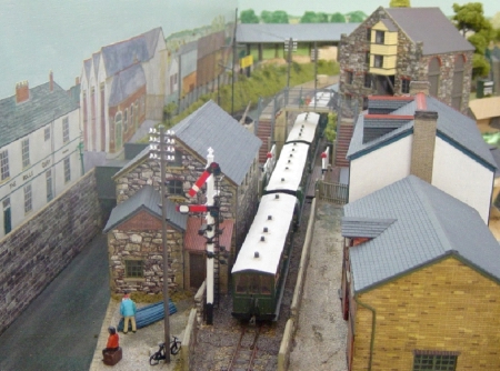
Model
Signalling on the Layout |
The signalling contributes a lot to the overall appearance of a model. The
various visible elements of signalling system are modelled carefully, just
like any other aspect of the model.
|
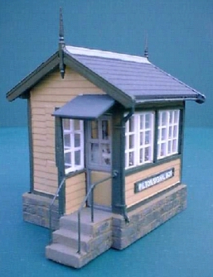
Signal Boxes, Huts and Ground Frames |
Each of the three signal boxes on the L&B were different in design, and
their construction is described site-by-site in the following sections.
Generally, interiors are fitted to signal boxes, using commercially
available whitemetal parts.
The signal huts at intermediate stations were quite rudimentary, and are
scratchbuilt from thin ply and plastic sheet. The doors are left open, so
that the tiny “knee” frame is visible within.
Ground frames are represented in the model, where their location is known
from photographs (i.e. Pilton and Lynton), although the type of frame
modelled is not necessarily 100% accurate.
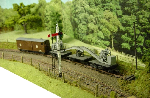
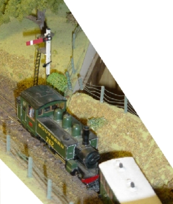
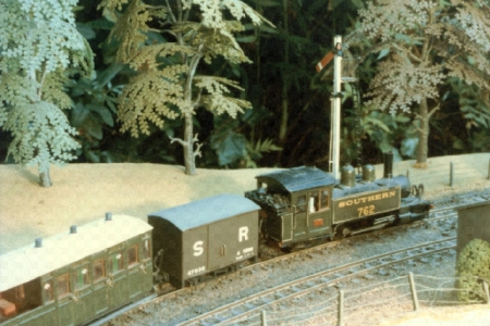
The actual signal structures on the model represent the signalling as it
was in the latter days of the line’s operation. There are a mixture of
wooden post signals with lower quadrant arms, lattice post lower
quadrants, together with a few typical SR rail-built signals – mostly with
lower quadrant arms, but one (Woody Bay Up Home) with an upper quadrant
arm.
Some signals have been completely scratchbuilt, with stripwood or Code 55
bullhead rail posts, and fittings fabricated from brass and nickel silver.
However, the excellent Model Signal Engineering range of etched brass
components have been used more recently. In particular, their lattice post
parts cannot be beaten by scratchbuilding (I know, I tried – once). I have
assumed that LSWR components are the most appropriate in terms of the
style of arms, lamps, etc.
On the model, the functional point machines, signal relays and cranks are
obviously installed well out of sight under the baseboards. To give the
correct appearance on the model itself, non-functional point rodding,
cranks, etc. are added to each layout, following the correct routes from
the signal box to the points. On some sections, this rodding uses square
steel wire running in tiny stands, assembled from etched brass components,
between etched brass cranks, which were bought as a pack many years ago.
More recently, I have used round brass rod (the L&B had round point
rodding) running in stands made by drilling holes in small plastic “T”
section material. When painted with rust colour, the effect is quite
acceptable from normal viewing distance.
The L&B facing points were mostly fitted with fouling bars, unusually
installed outside the running rails. As the lever for a set of points was
moved by the signalman, the economical facing point lock mechanism caused
the fouling bar to rise above rail head level as the lock disengaged, and
fall again as the lock engaged after the points moved. Clearly, if a train
was approaching the points, the fouling bar would be unable to rise, and
the points would remain safely locked.
These fouling bars are represented in the model by a length of square
steel wire soldered outside the rail head just below the upper surface,
and a crude representation of the rodding is added.
Ratio plastic telegraph poles are installed on the layout, at the
locations shown in photographs. These poles are cut down to give the
correct number of insulators. In addition, based on photographic evidence,
there are various places where insulators were provided on buildings, and
even on a signal post, to allow telephone and tablet instrument circuits
to reach the desired locations.
The signalling implemented on the model is currently as follows:
The overall architecture of the model L&B signalling is currently as shown
in the following diagram:
Signalling power is derived from a single Radiospares 230V/15V dual
secondary transformer housed in a box, via radial 15 Volt a.c. feeders to
each station. Because of the use of a single transformer, connectivity
between a.c. power sources and tokenless block circuits has been
standardised, since otherwise it is possible to create short circuits via
the TBS return conductor.
The transformer secondary windings have separate fuses; one secondary
feeds Lynton and Woody Bay and the other feeds Pilton and Barnstaple Town.
The standard power supplies at each station include a series 15 ohm
resistor, slightly reducing the voltage on the point machines to improve
their life, and also limiting fault currents. The inclusion of these
resistors means that points and level crossings should be operated
sequentially.
The
hand-built wooden post junction signals at Lynton were installed when the
layout was constructed during the 1960s, but were not initially
operational.
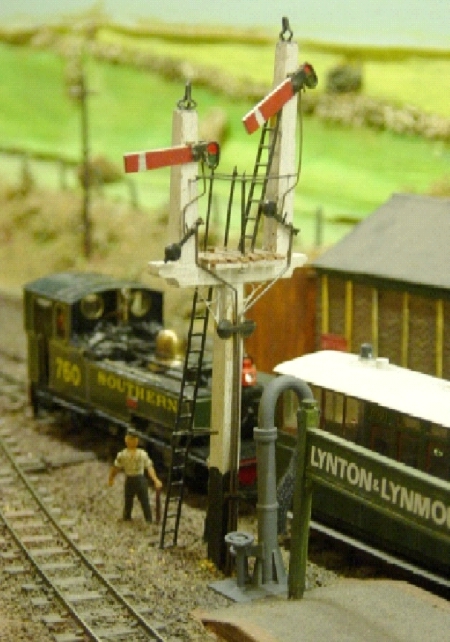
Lynton Up Starting Signals
Points were originally operated by solenoid
point motors, which proved unreliable. The lever frame and mechanical
interlocking was built around 1980, and was installed on the layout
itself. The Tokenless Block equipment, block shelf and electric lever
locks were added a few years later.
Mechanical operation of points and signals is
by direct rodding from a hand-built lever frame next to the model signal
cabin at the station. The lever frame incorporates mechanical interlocking
between points and signals. Levers are not necessarily arranged in
accordance with the prototype numbering (which is not known).
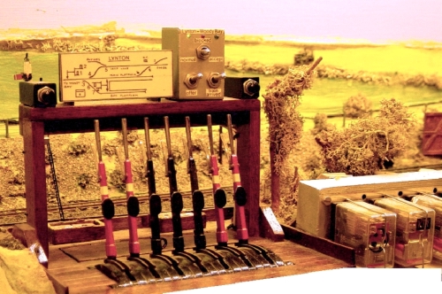
Lynton lever frame (l) with its Tokenless Block instrument, and the TBS
relay set (r)
Traction switching is achieved via a single microswitch on each point
lever in the locking frame. Signal On detection is via a similar
microswitch on each signal lever. Due to the simplicity and robustness of
the mechanical rodding, no local detection of point position is provided
in signal controls.
Tokenless block for the single line section to Woody Bay is provided, with
a block instrument on a block shelf behind the lever frame. The TBS
interfaces to electric lever locks on starting and home signals.
The run-round crossover and goods yard points are locally operated by
means of an unlocked 2 lever ground frame located next to the run-round
loop.
The model of the small signal box at Lynton was scratchbuilt some 40 years
ago. Signal
operation at Lynton has become unreliable, and some repair work is
currently needed to render the home signals fully functional.
A minor change to the point control and the mechanical locking is also
necessary to provide flank protection for passenger trains, to comply with
the prototype. This error has emerged in the light of further research.
Signal lever locks may be replaced with the more recent standard design,
to allow them to be manually released in the event of failure of the
Tokenless Block system.
It is planned to relocate the ground frame for the run-round and goods
yard points to the correct place at the end of the bay platform.
Scratchbuilt wooden post and rail-built signals were installed at Woody
Bay when the station was built in the early 1970s, but they were not
operational at that time. Points were originally manually operated by
rodding.
The Woody Bay lever frame was constructed and commissioned during 2000/1,
and the signals were made operational at this time.
Up end points are controlled by Fulgurex machines. No. 5 points
(double-ended) have a non-standard arrangement for traction power
switching (A end switched by N-/N switch, B end by R-/R switch), as the
point machines have insufficient contacts for two sets of traction
switching using the normal method using N and R contacts. This leaves the
possibility of brief short circuits if the points are moved whilst trains
are running.
Up end signals are motor-operated, using Fulgurex machines fed via local
point detection contacts. This solution was adopted because, at the time,
I had no suitable large relays to drive them, and experiments with Memory
Wire, although promising, appeared to show the need for frequent
adjustment to cope with temperature variations.
The down end points are controlled by a Lemaco machine. Down end signals
are semaphores operated by modified 12 Volt Post Office 3000 type relays,
whose contacts also provide the "signals on" detection interfacing to the
tokenless block.
Woody Bay Up Home signal – the only upper quadrant on the line
A free-standing 7 lever Model Signal
Engineering (MSE) lever frame is provided, with electrical switches for
point and signal operation. Interlocking between points and signals is via
a mechanical locking frame. The lever frame is connected to the station by
two 25 way cables. Levers have the original L&B numbering.
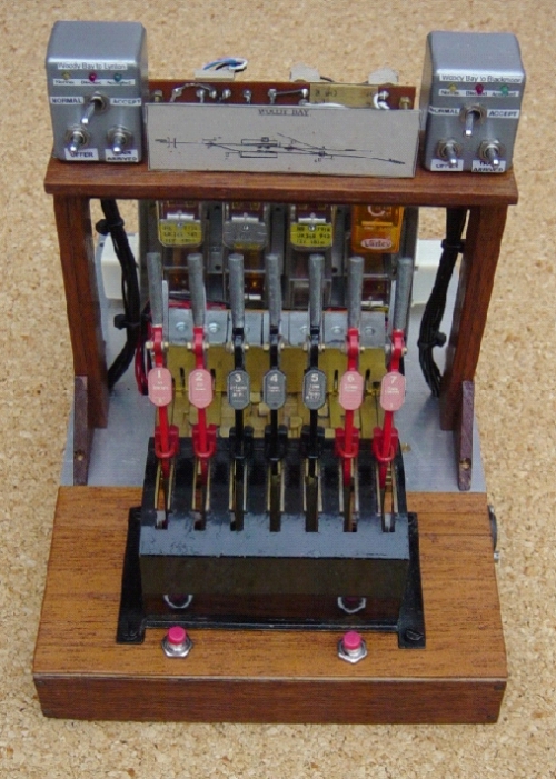
Woody Bay Lever Frame. The TBS relay sets are behind the locking frame
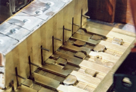
Mechanical locking tray at Woody Bay, with electric lever locks (l)
Tokenless block is provided for the single
line sections towards Lynton and Blackmoor.
The lever frame is modelled with the correct orientation, as per the
prototype, where the signalman faced away from the track on the up
platform (Lynton to the left, Blackmoor to the right). However, as
currently installed, the model station is "the wrong way round", leaving
the operator with Lynton on his right and Blackmoor on his left. This is
not a serious problem, as the L&B lever numbering was not particularly
logical (it may originally have been intended to provide distant signals
approaching loops, rather than starting signals). The biggest difficulty
is that the (non-prototypical) block instruments are at the "wrong" ends
of the block shelf in this situation.
The signal hut at Woody Bay is scratchbuilt from thin ply.
Woody Bay Down Starter – an original Evans O’Donnell wooden post lower
quadrant signal
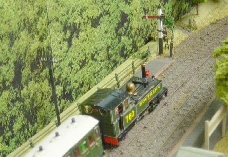
Lyn passes Woody Bay Down Home signal – a tall rail-built lower quadrant
The Up starting signal and the Down Home
signal, which are currently motor operated, will be converted to relay
operation, to bring them into line with other stations, and to allow the
point machines to be reused elsewhere.
Pilton Yard was built around 1980, and at that time all points were
operated by individual toggle switches via mechanical rodding. No signals
were provided at that time.
An interim switch panel was built in 2003, and outside equipment assembled
and tested prior to its final installation in stages during 2004.
Outside equipment on each baseboard is connected to the lever frame by
D-type cables. The Down end points and signal are connected by a 9 way
cable, and the Up end points and signals via a 25 way cable to a
distribution panel, from which three further 9 way cables link to Pilton
Road crossing, Braunton Road crossing, and to the Down Home signals. A
further connector is provided for eventual slots from Barnstaple Town (SR)
Signal Box.
Signals, points and level crossings are all electrically operated from an
interim lever frame consisting of 9 unlocked switches. This unit also
houses the TBS and block instruments.
Pilton Interim Switch Panel, with block instruments
The Down end yard exit points are operated by
individual local switches and rodding, rather than a ground frame. No
electrical release or detection in signal controls is provided.
The Up end loop and yard exit points are operated by Lemaco point
machines. The trap points at the up yard exit are non-functional, due to
restricted space beneath the layout.
A MSE LSWR-type lattice semaphore Up Home signal is installed, and is
operated, via a local point detection contact, by a modified Maplin power
relay.
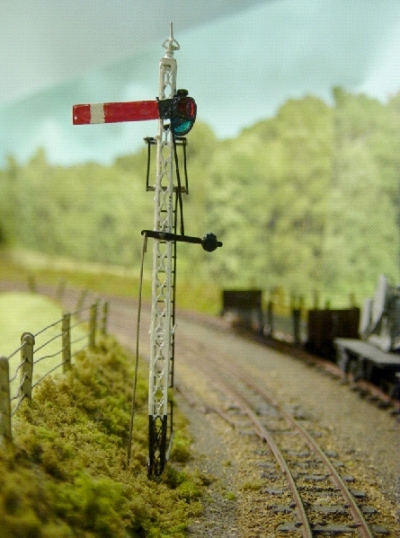
Pilton Up home signal. The dummy fouling bar is just visible to the left
of the track The
Up Starting signal is constructed from an MSE lattice post with lower
quadrant arm. It is operated by a modified Maplin power relay. This signal
is actually attached to the fellmonger's yard scenic add-on that attaches
to the front of the layout, and so it is plug-coupled to the main
baseboard. The local point detection circuits allow the up starting signal
to be cleared either for moves from the up loop or from the yard. With
hindsight, this signal is a little too tall.
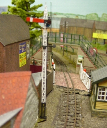
Pilton Up stating signal, with Pilton Road crossing in the background
The Down Home signal, with
its main and shunt lower quadrant arms, is constructed from an MSE
whitemetal "wooden" post, with rather complex platforms to allow access to
the two lamps and arms. The shunt arm is provided with a black circle,
although the use of such an arm appears to deviate from SR standards of
the time. The red spectacle on this arm is of reduced diameter. Three
groups of operating levers and balance weights are provided in an attempt
to represent the slotting of these signals from Barnstaple Town L&B box.
The main and shunt arms are operated by two modified Maplin power relays.
A train for Lynton passes Pilton Down Home signal; the second arm is for
entering Pilton Yard
As Pilton had no down
starting signal, it was necessary to simulate one, to allow the TBS to
operate correctly. This was achieved by means of a relay circuit operated
by the lever lock release.
As yet, there is no interlocking between points and signals at Pilton,
although signal clearance depends on local point detection. Yard points
are all operated by individual local switches at the front of the layout
(actually in the mill leat!).
Mk2 Tokenless Block units are provided for the sections towards Barnstaple
Town and Chelfham.
Pilton signal box is constructed using parts from a Ratio plastic kit,
extensively modified to resemble the prototype as closely as possible. The
interior includes models of the two Tyers No. 7A tablet instruments that,
here alone, were located in the signal box.
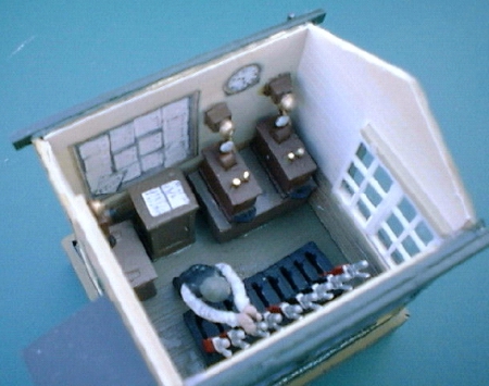
Pilton Signal Box – the tablet instruments are the boxes with white
indicators and brass plungers (top right)
It would be desirable to link the down end
yard exit points, and control them from a single lever unlocked ground
frame, similar to those provided for the quay siding and at Lynton, since
the present switches are rather inaccessible (buried in the undergrowth!).
It is intended that the signalling will be
controlled from a remote 9 lever MSE lever frame (i.e. a similar design to
Woody Bay). The locking conditions for this lever frame have been defined
and tested by simulation. More recently, advice has been sought from the
specialist on L&B signalling about the most probable lever numbering for
this lever frame.
Pilton Road crossing was constructed in 2003. It is electrically-operated
by means of a Fulgurex point machine, with gates sequenced in pairs.
Detection is provided by switches on the point machine itself.
The crossing is controlled from the interim switch-based lever frame at
Pilton, via a local control unit hidden in bushes. Signal clearance is
conditional on the crossing being proved open to trains.
The operation of the gates in pairs is not very pleasing, and the gates
move too quickly. The crossing unit could be rebuilt with a mechanism like
that at Braunton Road, as time permits.
|
Rolle
Quay Siding Ground Frame |
A single lever unlocked ground frame is fitted. This is built from parts
of an old GEM lever frame, and set into the surface of the yard outside
Baker's Mill. The ground frame is (correctly) not detected in signal
circuits.
The model of Braunton Road crossing was constructed as a removable unit
during the 1990s, and incorporated in the loft layout more recently.
The electrically-operated fully-sequenced overlapping gates are driven
from a single Triang X04 motor via double worm gearing. An arm rotates
slowly round slots in four interlocked Perspex discs, which each move
through 90 degrees in turn. Detection microswitches cut the motor power
when the arm reaches the end of its travel. Each gate is driven from one
of the Perspex discs by phosphor bronze wires and cranks. The drive method
is a distant memory from the Meccano Magazine in my youth!
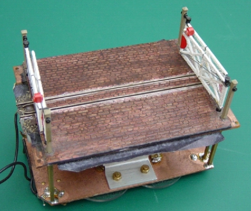
Top view of Braunton Road crossing mechanism with its overlapping gates
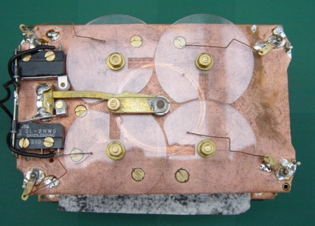
Underside of the same crossing. The brass arm rotates 360 degrees
anti-clockwise to operate the gates
The crossing is controlled from the interim
switch-based lever frame at Pilton, via a local control unit, allowing
either remote control or remote release and local control. The control
unit is housed in the doorway of North Gate House, adjacent to the
crossing.
Signal clearance is conditional on the crossing being proved open to
trains. To achieve this, a "Gates Open" detection relay is fitted on the
operating mechanism to provide multiple contacts for local detection of
the crossings in signal circuits.
The appearance of this crossing is most satisfactory in operation – one
can almost imagine the crossing keeper walking round opening each gate in
turn….
This station was constructed in a short
period in 2003/4. Motor operation of the points and relay operation of the
L&B starting signal were included from the outset.
Points are controlled by Fulgurex point machines located under the
baseboard. Switches on these machines switch traction power to the track.
The trap points on the run round loop and the transfer siding operate
correctly in conjunction with the main points.
The down starter is constructed from Code 55 bullhead rail, with MSE
components used for arm, platform, operating levers, etc. The model
includes a representation of the operating lever providing the "slot" from
the main line signal box. The signal is controlled by a relay mechanism
based on a modified Maplin power relay.
The up home signal is not fitted, but a design has been prepared for a
dummy colour light signal visible to the operator.
Initially, the station is controlled from a non-interlocked switch panel,
which has been interfaced with Mk2 Tokenless Block equipment, although
signal clearance is not currently dependent on TBS lever lock outputs. The
lever numbers are arbitrary, as the original numbering is not known.
Provision has been made in the design for future slotting of signals at
Pilton from Barnstaple Town SR signal box.
Barnstaple Town L&B signal box was unusual in having windows round all
four sides. The model was constructed from the parts contained in two
Ratio kits, extensively redesigned to represent the prototype. The result
is quite pleasing.
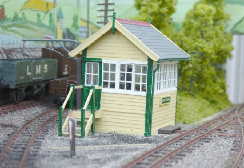
Barnstaple Town Signal Box
The section of the standard gauge side of the
station that is included in the model is purely static, has no points, and
the down starter is merely painted on the backscene, as is the signal box
for the swing bridge over the River Yeo.
Bob Barnard
barnard.bob@btinternet.com

|