|
wiring light emitting diodes (LEDs)
When installing lighting in a locomotive you
have a chose of either lamps or LEDs. There are reasons to chose one
over the other. Factors to consider are life, cost, size and ease of
installation. Lamps have been with us for a long time. LEDs are newer
and the technology of LEDs is changing for the better.
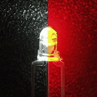
The first visible colour LEDs were red followed by yellow and then
green. In the last few years white LEDs have also become available. The
first white LEDs had a blueish tint that did not look like an
incandescent locomotive headlight. Recently the Golden-White, Yeloglo
and Sunny-White LEDs have changed this. These new LEDs produce colours
that are closer to that of an incandescent lamp. These new LEDs are now
installed in some of the new locomotives, supplied with some decoders
and available through many model railroad suppliers. The cost of LEDs is
just a bit more than lamps, but well worth it over time. When installed
correctly an LED will outlast the locomotive.
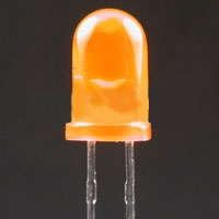
LEDs are available in different sizes. They run from the jumbo at 10 mm
to a very small “chip” size that mounts on circuit boards. The common
sizes are 3 mm and 5 mm. The 3 mm is the best for HO headlights. LEDs
are also available in range of colours. Red, green, yellow, blue and
white are the common colours. The LEDs that are made to resemble the
yellow-white appearance of colour of an incandescent lamp are the
Golden-White, Sunny-White and Yeloglo. The Golden-White is made with an
amber colour epoxy that filters out some of the blue. OK when on but
shows the amber colour when off. The Sunny-White and Yeloglo LEDs have
the incandescent appearance when lighted and clear when off.
LED's are quite different to light bulbs.
Light bulbs are designed to work on a voltage, LED's can work on almost
any sensible DC voltage if you have a correct value resistor fitted.
Resistors are relatively inexpensive and basically restricts the current
passing through the LED, as the LED's has no current limit itself. If
you put an 3 Volt LED on 12V power with no resistor it would be
extremely bright for a fraction of a second before it blows.
To connect LED's into a circuit, it is advisable to know a little about
Ohm's Law, a few basic formulas is all that's needed.
The figures you need to calculate the formula is the voltage you wish to
work from, the current you wish to pass through the LED, and the forward
voltage of the LED. The forward voltage can be found in the data sheet
for that particular LED, it is the value of Vf, around 3.4V for White,
different colours have different values.
Ohms law formula is V = I * R.
As we wish to calculate resistance it can be arranged to say R = V / I.
|
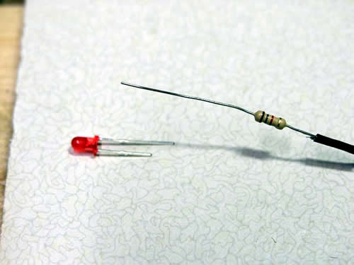
Connecting one LED and one resistor |
For example lets say we have a 12V supply,
and wish to run one Blue LED. We know the forward voltage Vf is 3.4V,
and we wish to pass 20mA (0.020Amps) through the LED.
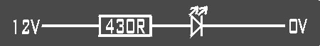
R = (12 - 3.4) / 0.020
R = 430 ohm resistor.
Connecting two LED and one resistor
|
Connecting two LED and one resistor |
As we have plenty of volts to drop across the
resistor we could add another LED in the circuit which would make the
circuit more efficient. At the moment the resistor will get warm
depending on power dissipation of that resistor, the reason for heat is
that you are converting energy to heat which is wasted power. By using
two LED's there re less volts to loose across the resistor, it will
still be the same current as passing through one LED, in effect you are
getting extra light as its two LED's, and less heat being generated.
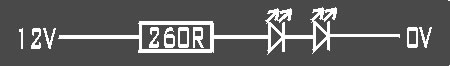
R = (12 - 3.4 - 3.4) / 0.020
R = 260 ohm resistor.
Calculating resistor power
Power is measured in Watts, things like light bulbs are measure in
Watts, most of the power is heat as a light bulbs is effectively a
resistor.
It is possible to calculate the power rating of the resistor required.
P = (V drop) * I
For one LED and one resistor at 12V
P = 0.172 watts
For two LEDs and one resistor at 12V
P = 0.104 watts.
Most of the time the rating of the resistor doesn't matter as they are
usually 0.5watts which is plenty, but if you were to use surface mount
resistor you would need to be aware.
|
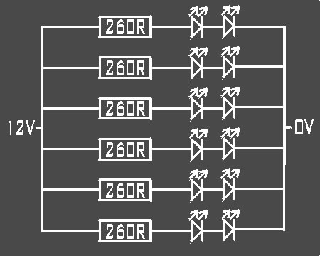
Connecting LEDs in series and parallel |
The above methods of connecting LED's was in
series, if you wished to have many more LED's in the circuit you can
basically multiply up the circuit across your power source to have as
many LED's as you desire, this is where you may need to take care of the
resistor heat, if you have many LED's in a small box with the resistors,
all of it could get a little warm.
Some companies, such as EXPO Tools supply
LEDs which are 12V ready. If you find the lights too bright, just add a
resistor. I tend to use 2Kohms or 3Kohm resistors.
|
How
you can determine anode and cathode of LED |
Most
common method
When you purchase an LED … longer leg is anode while shorter leg is
cathode. What if you have cut the two leads to same length ?? read on …
Method 2
- Take one resistor between any value between 100Ohm to 500Ohm and
connect it in series with the LED on bread board.
- Give a supply (from 3 to 9V). If LED glows, lead connected to VCC is
anode and other one is cathode.
What if you don’t have breadboard or you are too lazy (like me ) to do
this testing …
Method 3
- Take multimeter and keep it on Diode
testing mode.
- Connect one lead of LED to COM probe of DMM and another to RED probe.
- If you get some reading on DMM, then lead connected to COM is cathode
and other one is anode. If not reverse the LED and recheck.
What if you feel (like me ) this method is also too boring and time
consuming …
Method 4
- Take LED in your hand and look carefully at the place where leads go
into LED.
- Look at the border ring which is slightly projected out.
- You will find, on one side, this ring is flat. That’s the cathode !!!!
and other one is anode.
…and this will be True for almost all LEDs that you purchase from
general retail electronic shops.
Note: Some companies do not follow this convention for certain special
purpose LEDs.
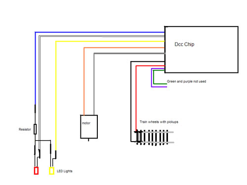
This is how to add direction lights to your
locos using DCC . The guide below, is just one ended, to show how to do
it for an HST or something like that. The train has been broken down to
show as simply as possible how it is done. In picture below we see a
basic DCC chip and a bogie from a diesel loco with wheel pickups in it.
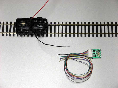
In this picture, you can see the RED and
BLACK wires are attached to the rail pickups on the wheels of the train.
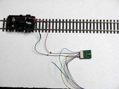
Now you can see the ORANGE and GREY wires
going to the motor. At this point this is all you would need to do to
get your train running on DCC.
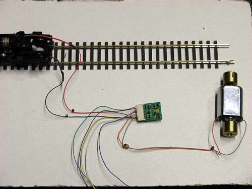
The blue wire is the next to be used, this
needs to go to the long leg of the LED with a resistor of the required
value between them.......
The next wire to be used is the yellow from
the chip, this goes to the shorter leg of the LED. All the wires are
left bare to show the connections, its best to cover the bare wires with
heat shrink when putting in trains, to stop any chances of a short.
(heat shrink is the black rubber stuff you can buy at Maplins)
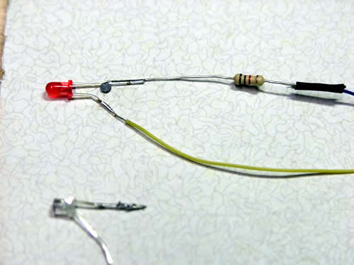
Remembering this is all in a train , all the
wiring may need lengthening and may turn out different in a train (shape
not basic principles). The next picture is a bit of a jump ahead as the
other LED is attached and has a jumper wire coming across from the other
LED with its shorter leg attached to the white wire. Jumper wire is in
red circle.

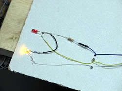
This is very basic, for a single ended loco.
Here is the loco going in 2 directions, first forward then backwards.
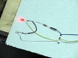
This is very basic, for a single ended loco.
Here is the loco going in 2 directions, first forward then backwards.
Problems..... You shouldn't have any, it
should work fine apart from one minor thing, that is easy to
change.......
If when you run your train, the lights are operating in reverse, (the
red on front and white on back), don't panic, just swap the orange and
grey wires around on the motor and that will sort it..... It is also
possible to change the CV values on the chip.
Below is another diagram for those of you who run 2 ended locos like
class 37s and 47s and you wish to have lights both ends.

DCC Supplies
now supply common anode bicolour lights. Bicolour lights
with common cathose are more difficult to install. Just
connect the common anode(+) lead to the blue decoder wire
(via the correct resistor), and the remaining wires to the
White and Yellow decoder wires (depending on your
requirement for Red or White lighting).
We always attach a Peco switch to our point
motors. If adjusted correctly, the polarity of the frog will be changed as
the motor throws. The green wire is attached to the frog, and the red and
blue wires to the track supply. It is always necessary to check that these
are wired the correct way around to avoid sparks!
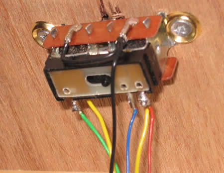
All we do to have indicator lights is to
extend the frog wiring and track power to the control panel.
LEDs will only work wired up the correct way,
With a bit of experimentation, it is quite easy to get the lights to come
on in the correct manner. We use 12 V LEDs supplied by EXPO Tools. As we
use DCC, we add the resistor.

|