|
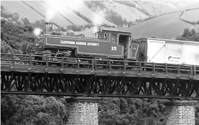
Building the Kerr Stuart 2-6-4T
After the success of the Dholpur 2-8-4
tank engine, I could not resist building one last locomotive; this time a
freelance design which typifies a class of colonial locomotive exported
to many parts of the world.
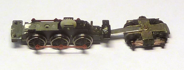
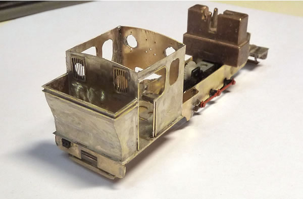
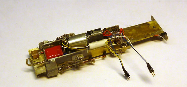
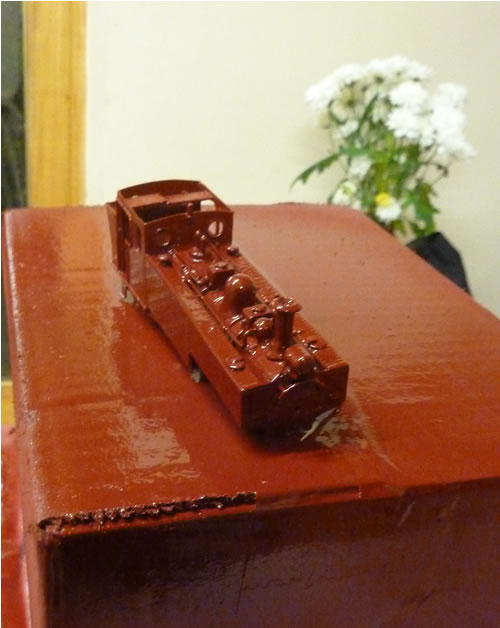
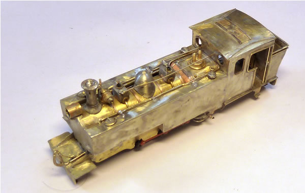
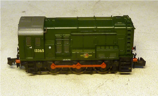 The new class 08 loco
ready for butchery.
The new class 08 loco
ready for butchery.
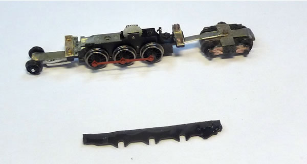
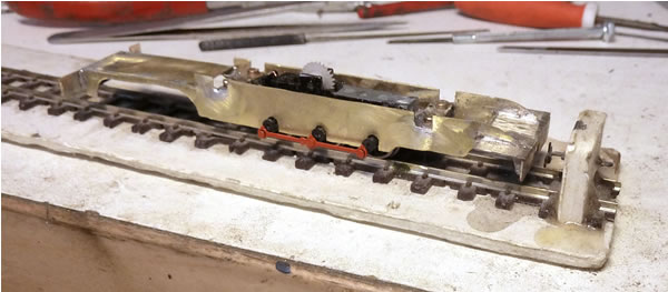
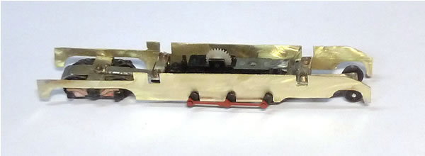
The bogie is fabricated and the chassis
modded. Next, the pony truck (inside framed for clearance inside the
cylinders). Once the wheelbase is established, everything else follows.
Note a small amount of side movement is allowed on the bogie pivot. This
is restricted by two small bent wires.
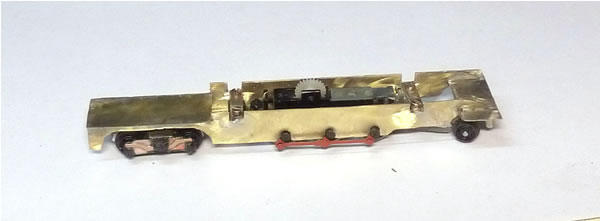
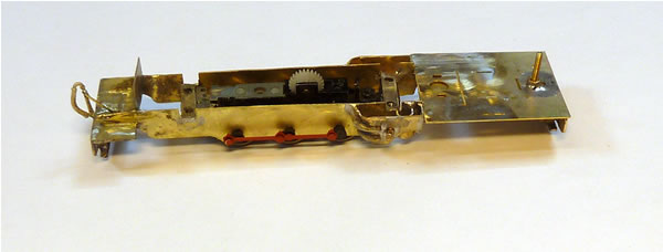
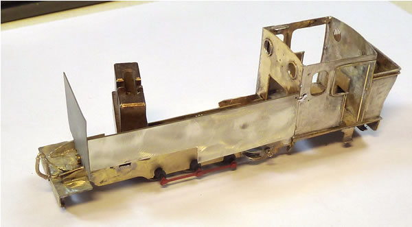
Here, the front pony truck is fitted and
the cross members screwed onto the chassis to correctly space the frame.
The side of the original frame are to be used as a template.
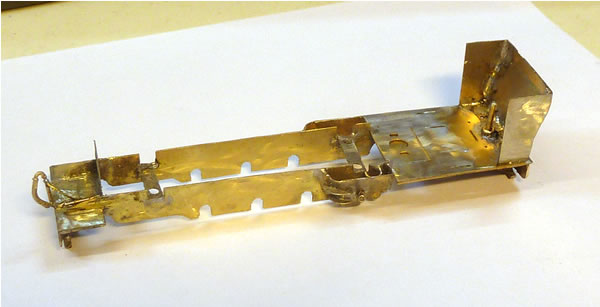
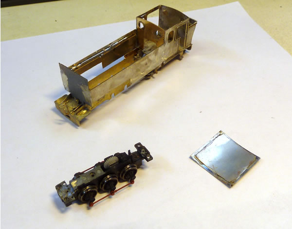
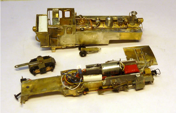
The frames, in hard brass, were cut out,
soldered together then cut to shape (Ahern style)
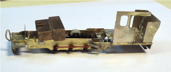
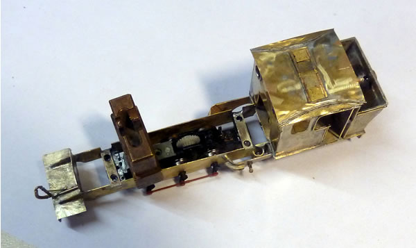
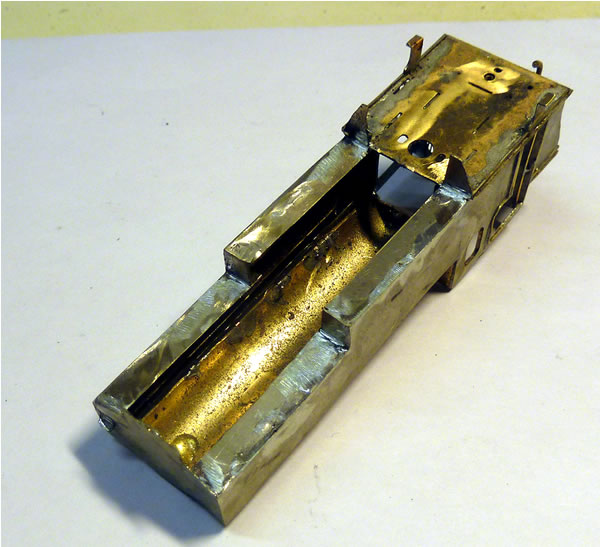
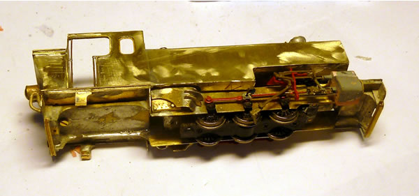
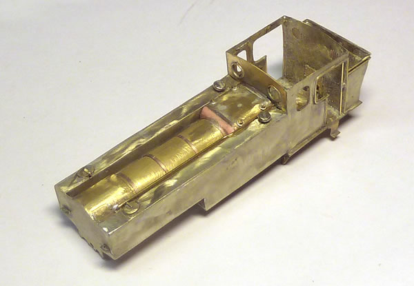
The inner chassis is now installed to the
frames with 14mm spacers added. The power chassis can be removed by
undoing the four screws.
Here coupling height is being check using
my jig.
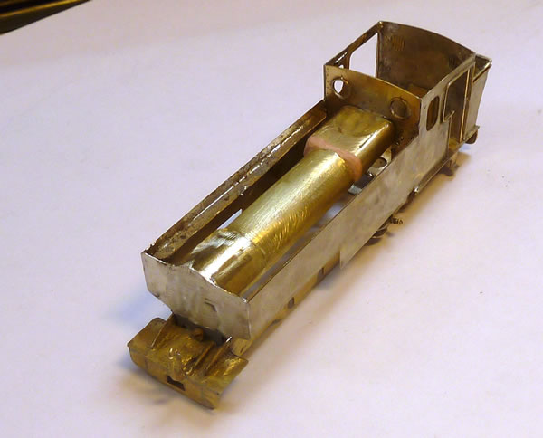
The first thing is the cab floor and
provided that is square and level, the rest follows.
The roof will be removable using a 14 BA
C/S screw.
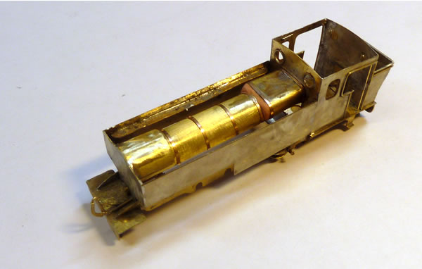
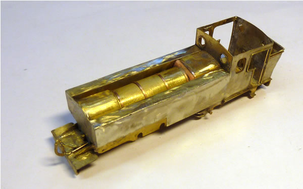
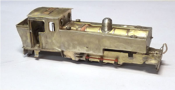
Tank bottom fitted. They will be filled
with lead shot.
Here, the blower pipe is in as are the washout plugs, tank fillers and
vents.
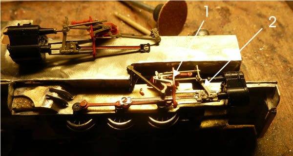
1 Eccentric Crank (Return Crank) 2
Eccentric Rod 3 Reach Rod 4 Lifting Link 5 Lifting Arm 6 Reverse Arm &
Shaft 7 Link (Expansion Link) 8 Radius Bar
9 Crosshead Arm (Drop Link) 10 Valve Stem Guide 11 Union Link (Anchor
Link) 12 Combination Lever 13 Valve Stem
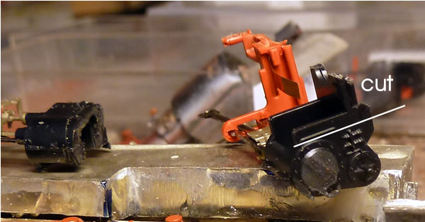
So, now we look at how to adapt the Roco valve gear (Roco 116295).
The normal movement in the crosshead is barely sufficient when fitting
to the 08 chassis as the cranks have a bigger throw than the original
Roco model. From now one, then, we have to do some serious butchery. I
use a metal tooth slitting disc to operate on the plastic. It gives a
great clean thin cut.
The first job is to super glue the slide bars to the red slide bar
holder, making sure that is the only thing glued! I use 'Zap a Gap'
which is a bit thicker and does not run up your arm or glue your hands
to your lips! I put a drop on a plastic syrface and apply the glue with
a thin wire. While this valve gear does come apart, I really try to
avoid this as each time one messes with it, the things are more likely
to fall off during service.
The cylinders are then cut at the back so the slide bars are as close in
as possible. The point shown seems to work for all these conversions.
Hidden behind the piston rod on the
crosshead moulding is a small spigot that prevents the crosshead moving
closer to the cylinder. This has to be very carefully removed. Once this
is done, you will have full movement. The combination lever almost comes
out at the bottom as this is simply a fork but that is OK.
The red crosshead support is then cut at the back so when rested on a
flat surface, the whole thing is parallel.
Now you can offer it up to the loco.
There is a variation here from one design to the next. In this instance,
the connecting rod is best fitted to the centre driver. This is always
preferable abyway as this is the driven wheelset.
The Roco cylinder has long stems which hold the piston rod and valve
stem. This is fortunate as in this case, to fit, the cylinder has to be
cut in half, just clearing the piston rod. It can be cut a bit more by
the way as the rod will stay put without falling out BUT CARE IS NEEDED.
The back of the red slide bar support is carefully pared at the back to
give a bit more clearance.
The positioning of the cylinder is critical
to make sure alignment is correct and the crosshead travel is OK.
I then put a drop of solder into the main journal of the connecting rod
and drill to a smaller hole to fit the crank pin. In this instance, This
is temporary, BTW but allows me to accuratly locate everything. At the
back of the journal, I have left a bit more solder thickness which will
act as a spaced between the coupling and connecting rod.
Next, the cylinder is sanded down to remove
the moulded cylinder plus a metal thickness all over. I have cut the
moulding back a little so the extent of the piston rod travel can be
seen Then we can start to build a new cylinder 'appliqué' and begin to
put the lot together.
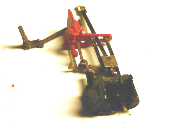
It is clear in the photo below how the fork
of the combination lever begins to pull away on maximum travel.
This shot also shows how the slidebar
support bracket is finally trimmed. I cut away the inner support as
shown just before fitting to avoid accidental breakage during handling.
You can also see how the space around the piston rod and valve rod
glands are filled with bodyfiller, trimmed when plastic with a sharp
scalpel.
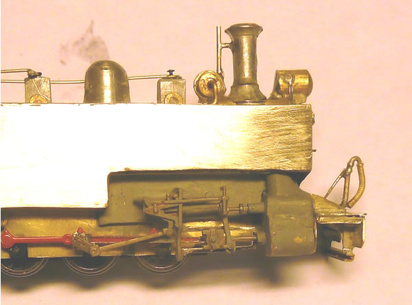
The centre crankpin is replaced with a
piece of wire, the cylinder is carefully located and glued into place
with epoxy.
The connecting rod is given a slight 'kink'
to make sure it never touches the front crankpin. The connecting rod
journal is now drilled out to 1.2mm exactly and the crankpin journal to
1.1mm. Huge care needs to be taken with the return crank. If you try to
force into the crank journal, it will break. If this happens, the
remains will need to be drilled out to 08mm and the pin replaced by
brass rod. Once happy with the result, the return crank pin should be
cut to length.
Once assembled, check that all is free running. At this point, the red
cross slide support is not attached. If this moves at all while rotating
the wheels, there is a bind somewhere. Once happy, the support can be
glued in place.
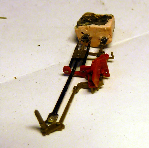
The complete gear. The body is filled where
possible with lead. The gap over the frames is where the chip is to be
installed, BTW. The final task is to cut back the rear of the cylinder
to give clearance for the pony truck.
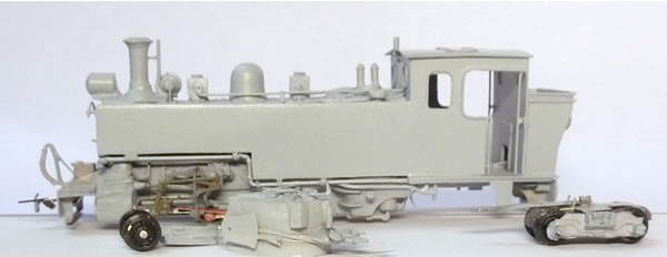
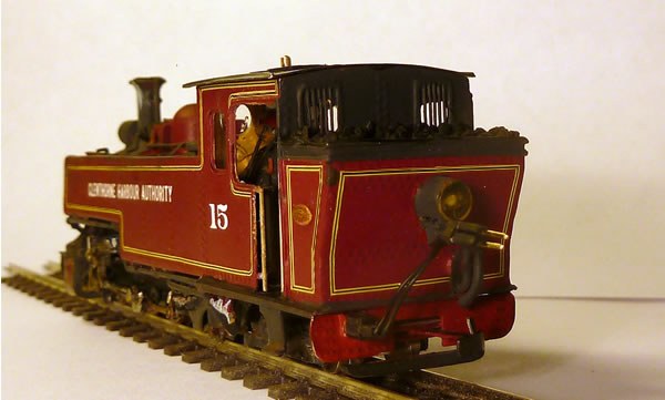
The body is sand blasted and then primed.
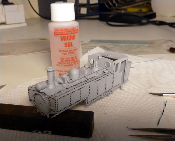
Archer transfer rivets are then applied.
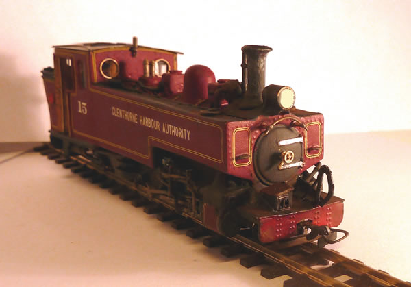
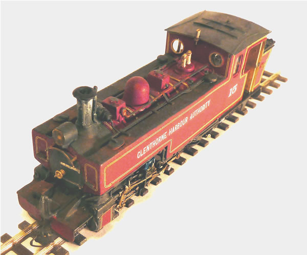
After detail painting, Fox lining is
applied.
Build time was one week and the loco ran
perfectly after a few small snags.

|