|
DCC explained

I was brought up in the era of
electro-mechanics. You could actually see what was happening in those days
and it made sense. Electronics are wonderful but my general understanding
is about that of ancient tribes observing an eclipse. Circuit boards look
to me like a mad mixture of tiny Liquorice Allsorts and Dolly Mixtures and the
sight of folks making up boards to their own design fills me with admiration.

Conventional model railway controls are based on the well-established
principle of varying the voltage to the track and thus to the motor of the
locomotive. This is usually achieved by a turning a ‘knob’, which actually
controls a potentiometer (some systems use a slider but the principle is
the same). This varies the output voltage to the track and thus to the
motor. To run fast the voltage is increased, to run slowly the voltage is
decreased, to stop the voltage is reduced to zero (or near zero). The
voltage range for OO/HO is usually 0-12 volts DC (direct current). This is
a direct descendant from the battery powered train sets of the 1950s (and
earlier).
This system is sometimes known as analogue control.
To control a single train or loco is simple, connect up and turn the knob.
Running more than one loco on the track however is more difficult but can,
of course, be done by introducing track sections and switches so that each
loco can be switched (isolated) when it is not to move.
Digital control has been around in one form or another for about 30 years.
Older UK modellers will recall the ‘Hornby Zero One’ system from the late
1970s. Modern systems are much more flexible and adaptable but use a
similar principle.
A constant voltage is applied to the track irrespective of the number of
locomotives on the track or where they are. Each locomotive or power unit
is fitted with a ‘decoder’ which acts as the onboard ‘section switch’ or
isolator. The locomotive only moves when its onboard decoder receives the
signal from the controller instructing it to switch on. The decoder also
‘decodes’ the signals from the controller instructing it as to which
direction it is to move in and at what speed. Most decoders also have the
facility to switch on/off loco lights, this can be done whether the loco
is stopped or moving and because the voltage is constant the lights are at
constant brightness once selected.
How does it control the speed when we have constant voltage? The
controller sends instructions to the selected decoder to allow pulses of
the full voltage to pass to the motor. The longer the length of the pulse
(known as its pulse width) and the greater the frequency of the pulse
results in the greater the speed of the motor. This is exactly what
happens with modern diesel and electric locomotives in the prototype
world. At full speed the voltage applied to the motor is in effect full
voltage all of the time.
It is because each decoder only responds to its own instructions (known as
its address) that enables multiple locomotives to work on the same track
and even run in the opposite direction (beware of collisions!).
Decoders for use in locomotives are often described as ‘mobile’ decoders
as decoders are also available for use with point motors and signals;
these are known as ‘stationary’ decoders and these function slightly
differently in that when selected by the controller they switch the full
voltage to the accessory because speed control is not a requirement in
these cases.
A badly running locomotive will still be a badly running locomotive,
miracles do not happen by using DCC however improvements in slow running
are definitely achieved by using DCC. This is because of the difference in
the operating principles explained above. Conventional DC control
permits a low voltage at a small current to pass to the motor when we
want to run slowly. In the event there is any dirt or the motor is
slightly out of balance (most are not balanced) and the voltage applied is
inadequate resulting in the loco stalling.
A DCC equipped loco has the full voltage applied at all times pulsed to
the motor, this results in smoother slow running. In my experience this is
in itself the biggest single advantage of DCC as even flywheel equipped
drives will run even slower under DCC than is possible with conventional
DC control resulting in much more realistic shunting moves.
Clean track and clean loco wheels are essential whatever system is used.
It is claimed that with a DCC system you only need two wires and in
principle this is true, just as with the simplest DC system you only need
two wires. Where DCC results in real savings in the complexity of the
layout wiring is where track layouts are at their most complicated AND
where you want to run more than one loco at a time.
Take for example a passenger terminal with adjacent goods yard accessed
from the same main line track with multiple point work, crossovers etc. In
a conventional DC wired layout you would need to install ‘cab control’,
switches, and isolated sections in order to work a passenger train and
shunt at the same time. With a DCC wired layout there are two wires taken
to each feed position, no switches, cab control or isolated sections.
Any loco can run at any time to any point on the layout.
|
Easier Multiple
Controller Control |
With Conventional DC control you can wire in two controllers using cab
control and section switches but it gets very complicated when three or
more controllers are required.
DCC controllers allow you to just plug in another handset, which has all
of the facilities of the original. It may be necessary, with some systems,
to purchase ‘extension plates’ but all but the basic units will allow at
least two control handsets to be plugged in. Using ‘extension plates’ does
however have the advantage of enabling the additional handsets to be
mounted away from the base control unit but retaining all control
features, an especial advantage on larger layouts or where there is a
shunting area remotely located.
Except for the very basic DCC control systems all will allow the operator
to unplug the handset and move to another plug in point and at the same
time the locos are still running unaffected. This can be a very useful
feature on larger layouts and even on smaller ones when two operators have
managed to get their cables twisted! This is a
feature our American cousins use extensively on their (usually) large (by
UK terms huge) layouts allowing train operators to actually follow their
train all around the layout. There are wireless DCC controllers now
readily available.
|
Correct operation of
lights |
DCC decoders are quoted as being one function, two function or more. This
can be confusing as what constitutes a function? In the case of a
locomotive that has running lights fitted that change when direction is
changed a two function decoder is required to make the lights work
properly. This is the one instance where conventional DC beats DCC!
In a
DC loco there is a rectifier (diode) circuit that prevents the wrong
lights coming on in the wrong direction of running, in DCC this needs a
signal for forward and one for reverse. However, decoders can be programmed
not only to switch the correct lights for each direction but can also dim
the lights (even flash) where appropriate – try that with DC control! A
one-function decoder can only switch on/off the
lights irrespective of direction. A loco parked in the platform waiting to
depart can have the correct headlights at the appropriate brightness even
when stationary. This can be done with DC but with additional
complications, it is standard with DCC.
Not everyone’s cup of tea but excites some folks. Personally
sound is growing on me provided that it is not turned full on. Sound has a place.
This results in the small
speakers not being ‘over amplified’ resulting in distortion. Factory
fitted sound systems are despatched set at full volume (that’s how they
are tested) and most purchasers do not realise that they can adjust them –
read the manual! It is easier to adjust sound, use it and enjoy it with DCC because the sound system can be adjusted simply by altering a CV (it's
easier to do than explain how to do it ! Just follow the manual.) DC
versions are now coming onto the market but these suffer because they are
not easily adjusted (if at all).
Sound in the model railway world is an interesting feature but we must
recognise that the laws of physics are still valid. Sound quality from a
speaker depends on the size of the speaker and the quality of the signal.
In N gauge and OO/HO we have to accept that speakers have to be tiny and
therefore cannot have the Bass – Treble qualities of our domestic sound
systems; accept that and you will not be disappointed BUT hear it before
you buy it whenever you can.
Locomotives running on DC are about as clever
as a bag of hammers. Chipped, locos are more intelligent than
George Bush and enormously more so than Sarah Palin! The new
chips are really very small and we were advised to choose the latest
Digitrax offering. The new Digitrax DZ 125 chip is similar in
size to the Lenz silver mini. This chip,
despite the instructions that come with it, is enabled for back EMF (BEMF)
(called 'scalable speed stabilisation' by the Yanks).
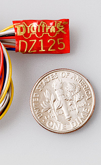
DZ 125
This offers better slow speed running and
also compensates for grades (a bit like cruise control).
At long last, the chips arrived and the exacting job of fitting them to our locomotives began. It was
necessary to virtually rebuild some of the older engines, and installation
into the L&B units was far from easy. Great care is needed to ensure that
there are no shorts in the system.
Chips can actually control other functions
too such as directional lighting. We have installed this on a few units
and it works very well indeed. The large amount of wiring needed to do
this raises challenges when working with such tiny rolling stock. I do
intend to fit sound to one unit, just for the hell of it!
The generic manual for these Digitrax chips
can be found
here
and the specific manual for the DZ125,
here
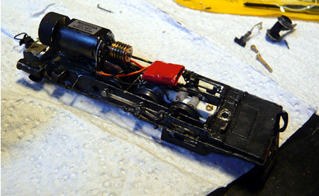
chip fitted to the
chassis of 'Taw' - click on image to enlarge
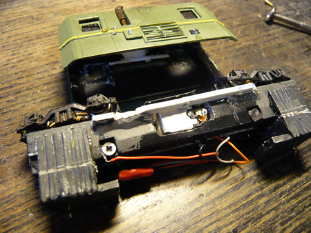
The motor unit of
the railcar converted. The part of the chassis which contacted the brushes had to be milled
away and the wires then attached to the brushes - click on image to enlarge
Once the Digitrax Zephyr outfit was
delivered, it was installed into the viaduct section of the model. The
main control box was fitted into a recess cut into the front of the
baseboard. This box is held in place with Velcro. In order to programme
locos, it is necessary to have a programming track...two leads come from
the control box to do this. We felt that this was another complication, so
the harbour branch of the viaduct section is fed through a double pole, double throw
switch to provide either track power or programming.
The leads to the UP5 remote sockets daisy
chain from the main controller. It is transferred from one panel to the
next using 8 pin DIN plugs/sockets. These also carry the track power.
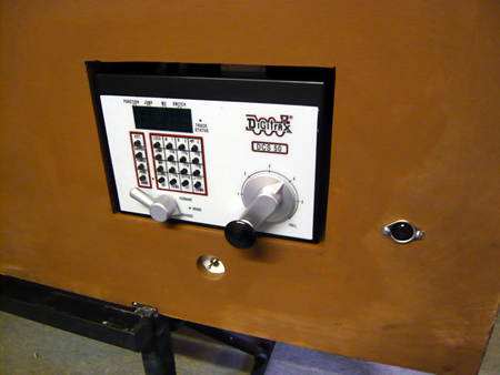
the main control box
fitted. Below is the switch to track for programming or power. The DIN
socket will feed to the harbour section
The box was 'lit up' and I have to say we
quite quickly got the hang of it. All the locos now had their numbers and
can be programmed to perform as required up to a point.
DCC promises to offer all
the characteristics that I required and there is no doubt you can programme each engine to do most things.
The programming of a loco
depends on altering a vast number of parameters. These are called CVs and
there are well over one hundred of them. These all have to fiddled with on
a programming track while your supper goes cold. In my opinion, a lot more
has to be devised to make the system user friendly.
I can honestly say that I
have not managed to get back EMF to work and I wonder if I shall ever be
able to properly programme these little engines.
DCC manuals seem to have been written by electronic nerds for
electronic nerds (or USA speak). I have to say that Lenz scores slightly
better in this respect, but Digitrax and NCE just make my eyes roll. Some
of the information is actually wrong and there is no logic (understandable
to British and French) to the way the manual is compiled.
There are a number of
forums available where help is at hand and this does ease the situation.
Thanks to some good
friends who are 'in to all of this' we hope to be able to publish here the
generalised programming necessary to get narrow gauge locos to run as they
should.
Bitter experience has
shown us that it is a very bad idea to use Peco point motors or others
requiring a CDU. In 20/20 hindsight, I would have fitted Tortoise
throughout.
Example:  Circuit symbol:
Function
LEDs emit light when an electric current
passes through them.
Connecting and soldering
 LEDs must be connected the correct way round, the diagram may be labelled
a or + for anode and k or - for cathode (yes,
it really is k, not c, for cathode!). The cathode is the short lead and
there may be a slight flat on the body of round LEDs. If you can see
inside the LED the cathode is the larger electrode (but this is not an
official identification method).
LEDs must be connected the correct way round, the diagram may be labelled
a or + for anode and k or - for cathode (yes,
it really is k, not c, for cathode!). The cathode is the short lead and
there may be a slight flat on the body of round LEDs. If you can see
inside the LED the cathode is the larger electrode (but this is not an
official identification method).
LEDs can be damaged by
heat when soldering, but the risk is small unless you are very slow. No
special precautions are needed for soldering most LEDs.
Testing an LED
Never
connect an LED directly to a battery or power supply!
It will be destroyed almost instantly because too much current will pass
through and burn it out.
LEDs must have a resistor
in series to limit the current to a safe value, for quick testing purposes
a 1k resistor is suitable for most LEDs if your supply voltage is 12V or less.
Remember to connect the LED the correct way round!
resistor is suitable for most LEDs if your supply voltage is 12V or less.
Remember to connect the LED the correct way round!
connecting to the chip
As a general rule, the
anode, (the longer prong) is commoned and connected to the blue wire of
the chip and the white and yellow wires go to the cathode.

|