When I started modelling the L&B in 009 scale in the 1960s, K's sold a range of whitemetal components for modellers, including some items for the then quite new
009. As these included a pack of castings for the correct L&B chopper couplers, my choice of couplers was simple.
Each set of the K's couplers consisted of a pair of cast coupler bodies, and a cast hook. The bodies were slightly over the scale width, in order to accommodate overscale thickness hooks, and the coupler heads were a bit on the small side. One of the bodies, and the hook needed drilling, and a small piece of wire then attached the hook. The coupler shanks were also drilled, and were pinned to the vehicle bodies a few mm behind the buffer beam.
The couplers worked well on my first rolling stock - 4-wheeled open wagons and vans, and I found that no pivoting was needed to cope with curves.
On bogie stock, the couplers were pivoted, leaving the coupler able to swing from side to side a little in a rectangular slot in the buffer beam.
I found that the cast coupler bodies could be bent up or down a little to adjust their height, ideally so that coupler bodies with hooks were very slightly lower than the non-hook ends, helping them to remain coupled when running over rail joints and pointwork.
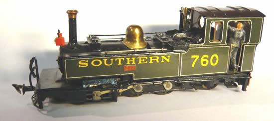
I worried that the white metal couplers would get damaged over time, so I decided that I would fabricate couplers for locos from nickel silver. Different pivot arrangements were necessary on some locos, as lead weights on leading trucks filled the space immediately behind the buffer beam, and some locos have spur gears immediately behind the rear buffer beam. In these cases, a small "pocket" of NS strip was soldered on the outside of the buffer beam, and drilled to take a wire pivot for the coupler. This is not the ideal location for the pivot, especially at the rear of locos, but it works quite well on my 18 inch minimum radius curves.
Coupling two vehicles involves manually lifting the hook (if necessary), lining up the coupler bodies, and then lowering the hook into the coupler body on the other vehicle. Uncoupling involves lifting the hook, and possibly jiggling the couplers about a bit to free the hook if the pair of couplers is under tension. I quickly decided that a custom-made tool would help with this. My preferred design consists of an empty BIC ballpoint pen, with a length of piano wire soldered into the brass tip, the piano wire having the last 5mm bent at 90 degrees.

My favourite type of uncoupling tool
K's eventually disappeared from the scene, but I still had a few K's couplers in stock. Then I discovered that Meridian Models had started selling chopper couplers. These consist of a casting containing a pair of whitemetal bodies (nicer than the K's ones, but probably even more over the scale width) and a fret of etched brass hooks.
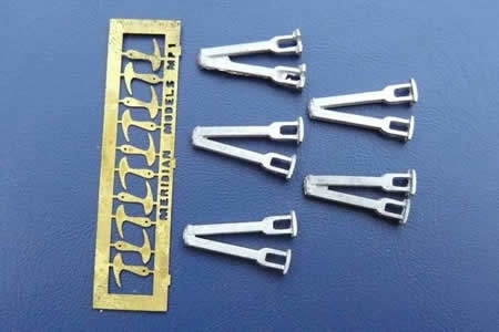
The contents of a Meridian coupling pack
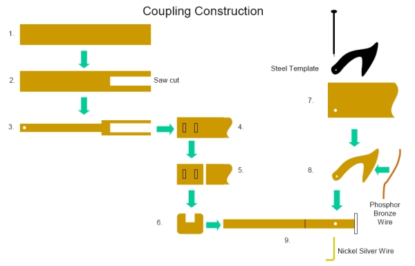
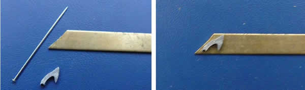
The Meridian hooks are flimsy, and to my mind slightly the wrong shape for L&B stock. So, I now make my own hooks from 1/32” brass strip (see Steps 7 and 8 of the section on
scratch building L&B couplers, below).
|
Long-term Experience and Improvements |
The cast couplers have in fact all lasted better than I could have expected; one or two couplers have been damaged accidentally, and I have had one or two instances of 40 year old K's whitemetal components becoming crystalline and brittle.
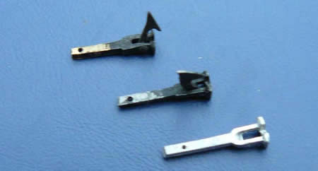
Various spare couplers from my stock. From the top: a
Scratch built brass coupler, a
K’s white metal coupler and an unused Meridian cast coupler body
As I have built more and more sections of the L&B, and established a layout using a mixture of old and new sections (some as much as 40 years old), I have found that the single hook couplers tend to uncouple at the occasional humps in the track (e.g. at base board joints). After a lot of thought, during which I contemplated
semi permanent coupling of some pairs of coaches, and/or the use of alternative types of coupler, I recently realised that most modellers accept the compromise of various exotic shapes of thin wire on the end of their rolling stock, so I tried extending the hook on some of my Meridian couplers downwards using a short length of thin phosphor bronze wire.
There is an optimum angle for this wire, so that under tension it pulls the hook down into position if it should lift a little in operation, but can still be lifted manually with the couplers not in tension, to uncouple vehicles. Initial results from this modification seem very promising, although more experience is needed before deciding whether to replace all the K's couplers (which cannot easily be modified, due to their
white metal hooks).

a pair of Meridian couplers, one with a scratch built hook with wire extension
Use of these modified couplings suggests the need for a modified uncoupling tool with two elements:
- A flat blade to push the wire extension up from beneath, to raise the hook
- A wire end to flick the hook up or down in the confined space between vehicles.
On a trip to Australia, a couple of small white LED torch key rings, with a very positive button operation to light them, were bought from a bargain shop for $2 - less than £1
each. They have had
coupling tools added, so that light is available to help see that
couplings are aligned. I am not yet sure that I actually like these tools
– I have a feeling it is useful to be able to rotate the tool in use, as
can be done with a pen case, but not a flat torch body. -

LED torch / uncoupling tool
|
Scratchbuilding L&B Couplers |
Scratchbuilt L&B couplers are quite straightforward to make. The following diagram illustrates the sequence of tasks to make a coupling: