|
Couplings, cowcatchers and pickups
doing it properly - one of Bob Barnard's locos fitted with Meridian
couplings
It has been said that the overhangs on L&B
Manning Wardles are actually greater than my stomach's. This does mean
that there are some serious difficulties in navigating fixed couplings
around the rather standard 12" radius curves of the 009 layout. The purist
will still go with scale couplings, which can be purchased from Meridian
Models. The problem is actually using them. Reaching over a layout with
a pointy stick and a shaky hand to lift up chopper couplings is not
everyone's idea of fun.
At County Gate, we have opted for the
Greenwich couplings, which look a bit like narrow gauge ones and offer
automatic coupling and uncoupling with magnets hidden between the rails.
There are a number of ways to make these
work. I shall first describe the method we use on our Backwoods MWs.
click image to enlarge
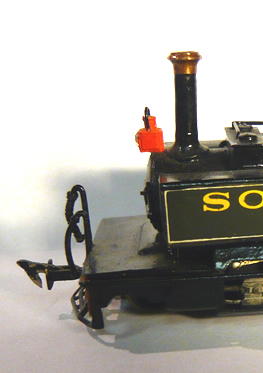
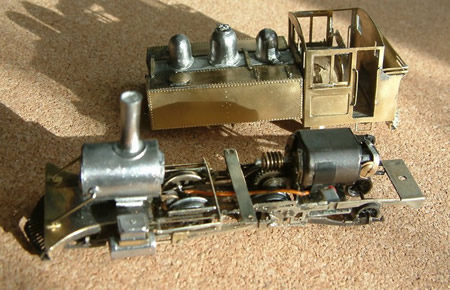
The front coupling does not have a lifting
loop and therefore, the cowcatcher can remain intact. We just extend the
buffer beam slot a little to allow for movement. We use fine steel
wire. Form a loop at one end and where best, bend a crank to bring the
coupling to the correct height. The Greenwich Coupling is cut short and
soldered to the end of the wire. Easy peasy.
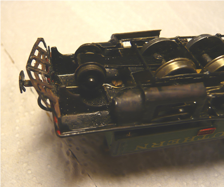
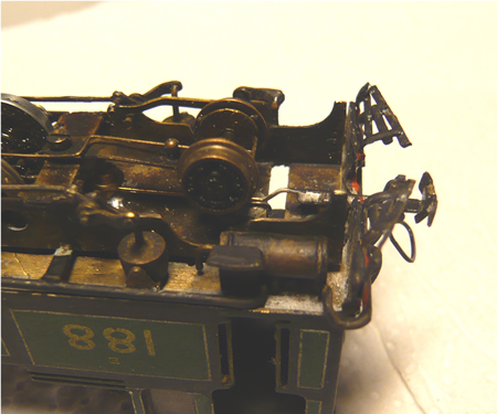
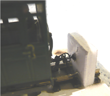
The rear is a tad more demanding.
click image to enlarge
We first have to solder a nut to the chassis
to take the fixing screw. Don't forget that the trick to solder nuts
without getting solder into the threads is to jam a cocktail stick down
the nut! The lifting loop of the Greenwich does need a lot of room, and we
are forced to remove the centre of the cowcatcher as shown. The
system does work very well although care has to be taken not to bend them
during handling. The spring of the wire offers the perfect 'give' around
corners.
The only loco that we are able to use fixed
couplings with is the Garratt which is articulated and with minimal
overhangs.
Some
locos do not offer a long enough length of empty chassis to
accommodate a spring wire. A
case in point would be the recently built 'Mad Mallet'.
A cruciform wire is soldered to the coupling
which retains two Bemo coupling springs. There you have it, a perfect
sprung coupling.
Here, the coupling is placed on a wire pivot.
It is retained in placed with a small washer. Two small sheets of brass
are soldered to the rear of the buffer beam to make the coupling box. In
some cases, the box would be formed by the existing chassis fitted to the
loco.
Another method I use is good for loco
couplings.
this was enough to derail
the following car
In an ideal world, one would use scale radii
on turnouts. Sadly, if this had been done at County Gate, we would never
have fitted everything in.
Now the worst offender for coupling lock is
our Baldwin 'Lyn' whose overhangs exceed even those of Jordan.
We now use a very fine spring wire which
slides in a small hole in a bracket soldered onto the cross member just
aft of the rear driver to centralise the coupling. This immensely improves
the situation but at a couple of tight double reverse curves Lyn was still
pulling the following car off the track. Our trains are intended to be
fixed consists, so we have been able to modify the coupling of the
adjacent bogie van.
new 'Lyn' coupling arrangement - click image to enlarge
The van coupling is free pivoting under the
bogie and centralised by a long spring wire
The coupling height of our rolling stock goes
back to the locomotives made by me in the early 1970s. For us it was 5.5mm
to the top of the buffer plate. It seems that this has subsequently become
a bit of a standard height, but no thanks to me! I have a short section of
track glued onto foam card with a 'buffer' glued to one end. Into the
buffer is glued a Greenwich coupler at the correct height. All stock
is visually checked against this.
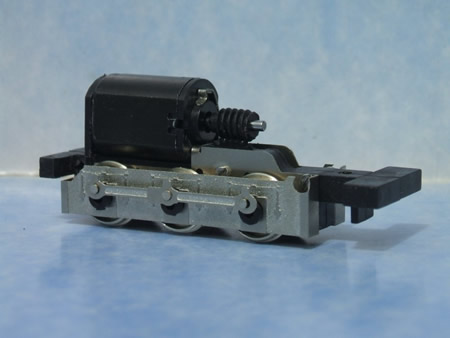
The Backwoods instructions suggest that the
electrical pickup be made using the phosphor bronze wire supplied
contacting the wheel treads. This is in principle a very bad methodology
because dirt picked up from the rails will gradually diminish
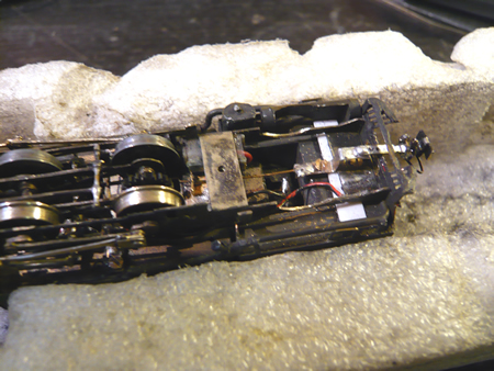
conductivity. Our chassis builder, Peter Wallace developed a different method.
click image to enlarge
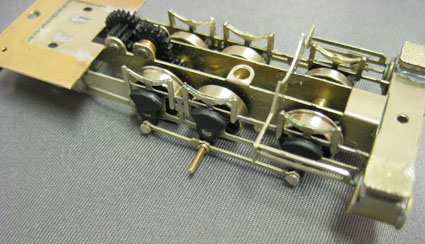
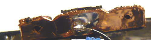
With space at a premium he solved the
problem by having one sprung wire contacting the flange, while the other
wheels had power picked up from the rear of the rims using spring
plungers. Sadly, after many hours running, the plungers began to fail and
have since been replaced with phosphor bronze sprung wire pickups acting
on the back of the wheels.
|
how
is the electricity collected from the wheels? |
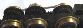
Without question, the worst place to collect
the power is through contacts acting on the wheel treads. Dirt will
inevitably collect on the treads and transfer to the collectors with the
result that sooner, rather than later, the loco will stall. Far better to
collect the power from contacts acting on the wheel rims or back of the
wheels. Sprung collectors are usual but very small plunger collectors are
available and are excellent.
Most modern chassis have insulated driving
wheels on one side only while the entire chassis is live with the opposite
polarity. This is now standard practice with say, Backwoods chassis. This
can have its drawbacks too. Great care is needed to make sure that pony
truck wheels can never touch the chassis.
Worse, some methods of installing couplings
means that they are live to the chassis. Unless you get it right, double
heading can cause a dead short. This means that you must always set up
your loco with a common polarity and never turn them around.
Another solution is the 'split chassis'
system. Here, the current is transferred through the axleboxes but there
are problems when scratch building to prevent the 'wrong bits of the loco
touching live bits' and thus shorting out. The axles of a full split
chassis system must also have an electrical break in the middle of the
axles. Thank goodness for Plasticard and epoxy glues!
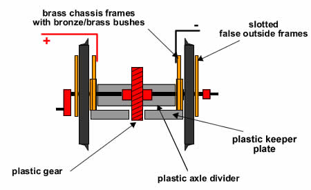
The advantage of the split chassis is that
there is no resistance due to collectors acting on the wheels. The spacers
between the chassis frames also have to be insulating. The drawing below
is how I built the chassis for my K1 Garratt. For this type of chassis, I
use a conducting lubricant.
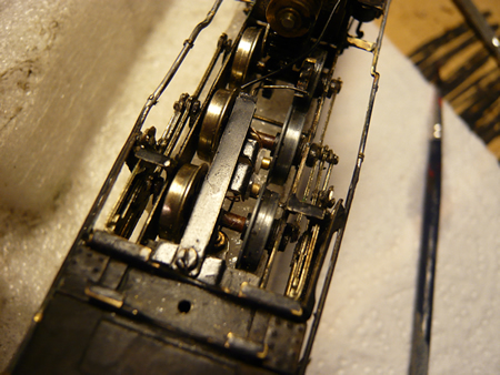
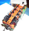
this Manning Wardle chassis has a 'live' side and plunger pickups on the
other
re-engineered Backwoods Baldwin chassis
One advantage of DC operation is that
electronic track cleaners can be employed. Quite often, a small resistance
between the wheels and rail are blown away with a micro jolt of high
voltage (they are also quite good for keeping your cat off the track).
If you are running DCC, you can programme an
additional start current which can often help.
Some products can be used on the track such a
Rail Zip or indeed a soft woodworking pencil. There can be wheel slipping
on gradients using some of these products.
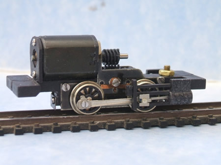
If at all possible, flywheels should be built
into the model. Their size is going to be small to fit in the average 009
body but is often sufficient to help with smooth running and help the loco
through dead spots. Sadly, space just cannot be found in all locos, such
as in the Backwoods 'Lyn' shown above.
We all expect good slow running these days.
This will mean a gear train with accurate meshing of gears and good
bearings are an essential part of the formula. Some Backwood kits have the
motor worm drive slightly offset. While this may work, I have found that
excessive wear can take place.
Some specialist chassis are constructed in
such a way that it is almost impossible to take them apart to effect
repairs. The standard Backwoods chassis are exceptionally difficult for
instance. If at all possible, assume that everything will eventually wear
out and need replacing.
Some chassis designs are simply asking to
wear out due to their construction.
Firstly, let's look at the much vaunted
expensive Roco outside frame chassis.
click on image to enlarge
the Roco 'rip-off'
Here, the axles are not in bushes but make
point contact with the die cast chassis. Very quickly there is wear and
the loco will no longer run properly. The plastic keeper plate also slowly
wears down. On top of all this, the Mashima motors supplied in the
loco very quickly develop a very rough spot when slow running. This is
another thing to look out for. These days, if at all possible, I remove
motors and run them light. In my view, there just should not be any rough
spots at all.
For reliable running, axles must be fitted in
proper bushes in brass or better still, bronze.
a properly bushed chassis by Victors Models (Sandy River No 19)
Equally, coupling rods and crank pins will
wear. This is particularly the case with chassis that are driven through
one axle as is the case with the chassis shown above. I now favour hard
steel crank pins and bronze bushes sweated into the coupling rods. If you
think this is a tad over the top, our first Backwoods Manning Wardle wore
out its crank pins and rods after 20 hours of operation.
This leads us on to the next issue. If only
one axle is driven, it is far far better to drive the centre axle in a six
coupled unit rather than an end one, as shown above. There is far less
binding and likelihood of wear. In my view, the best solution is to drive
all coupled wheels.
The Early Lilliput chassis did this and will
run forever given simple maintenance. True, they run too fast and the
motor is not the best but the coupling rods do not do any work so they can
be reduced to scale size with no concerns. My Baldwin, which has such a
chassis and is fitted with scale sized rods, ran 24/7 for a year in a shop
window. It still runs great now!
early Lilliput chassis
One chassis which potentially fulfils all the
requirements is the new
N Drive
Productions unit. They even
promise to offer them with outside frames. True, no
valve gear comes with it, but this is easy enough to add, using a fret
available from Backwoods Miniatures at £18. The drawback is that at
present, their construction is a part time job and as they become more
popular there might be some delivery delay. Hopefully he will find ways of
increasing production.
N Drive
Productions 6 coupled outside
frame chassis
0-4-0 chassis by
N Drive
Productions (£42)
I have always tested my chassis for 8 hours
running forwards and a further eight backwards, If any sign of wear showed
after this ordeal, the design would be re-engineered. That is, until I
bought the Roco chassis, which I assumed had been previously rigorously
tested. How wrong I was and the whole exercise has cost me hours of work
and £400!
By the way, it is worth keeping logbooks for
your locos so you can record the hours they have run.
There are, of course, those who just like to
collect locos...lots of them. But for those who are building a layout and
want their locos to look as good as possible, is it not time to take a
long hard look at the quality of running chassis? Costs are coming down
but there is no doubt that 'proper' locos are going to be more expensive.
What would you rather have, numerous toy trains or fewer proper models?
I have got thoroughly fed up with 009 bogies
and wheels supplied in kits. They are not very free running, often
inaccurate and if one is able to get them working, they can be very
delicate.
Mass produced N gauge equipment is, on the
other hand, very reliable. Simple solution...use N gauge gear. Our Lynton
and Barnstaple narrow gauge rolling stock sits on the rails rather like
sausage dogs - you really can't see the undercarriage! I hear anguished
purists bemoaning the use of such gear, but they are often same folks who
spend a lot of their time putting things back on the rails!
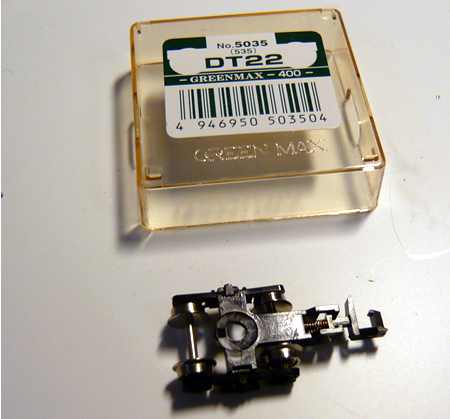
I have selected bogies produced by Green Max.
These are getting hard to find these days but are still available if you
Googler for them. We use DT 22 bogies for goods and DT 16
for coaching stock (or equivalents). The wheel bases are a bit shorter, which allows one to
place the bogies between the frames, where they are supposed to be, and
still get sufficient movement for 12" radius turnouts. At present,
there seems to be supply difficulties with Greenmax.
I have rarely found a Green Max wheel out of
'back to back' but I do check every one with a gauge. The additional
advantage of Greenmax wheels is that only one wheel is insulated so they
can also be used for current collection. I just pull out the knuckle
coupling and glue in a Greenwich version.
Green Max
goods bogie
|
getting power to the locos |
Many of our locos have small wheels and not
enough of them to be able to reliably collect current at all time to run.
In order to get more wheels to supply current, pony wheels can be used as
well as the drivers. The simplest method is to use just one wheel each
pony truck. With Greenmax wheels, this is simple.
Another method is to use the adjacent
wagon/coach as a current collector. Often, locos remain in a fixed consist
so under these circumstances this is a very good option. All our main line
trains that run under automation are connected to companion cars and they
almost never stall. We stick copper tape on the inside of one bogie side
(opposite side for the other bogie) and link up with thin flexible
multistrand wire to connectors to the loco. A dap of Copperslip grease
in the bearing hole will ensure good electrical contact.
self adhesive copper tape
attached to one side of a bogie. The pickup wire can be seen.
The connectors used are supplied by Express
models. Another advantage is that is is very easy to test a loco on DCC by
just plugging in with a lead.
Once you have soldered on the correct wires,
you will need to encase the joint in epoxy, otherwise the joint will break
in time.
The choice of wire as connectors is
difficult. They do have to be very soft and flexible. The best is that
supplied by DCC Supplies. They use it for DCC chips.
The plugs are inserted with tweezers and are
marked with a small spot of paint to ensure correct polarity.
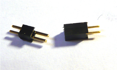
micro connectors supplied by Express
Models
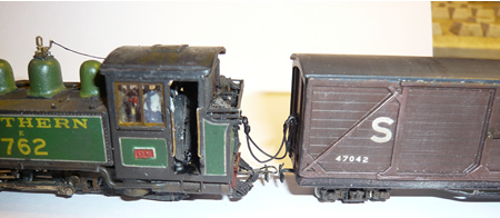
'Lyn' and her best friend!
I always advocate using 'companion cars'
connected to locos that run with fixed consists. The additional current
collection makes these trains almost 100% reliable. The problem at times
is that the bogies of the companion car are far better at collecting
current than the rigid chassis of the locos themselves. After a period of
operation, the locos become very reluctant to operate on their own.
Careful cleaning is needed and after a little coaxing, they will begin to
run again. I always let them travel a few circuits in both directions on
their own before reattaching to the companion car.
Despite best efforts, occasionally we find a
piece of rolling stock that just will not stay on the rails.
-
Check back to back
measurements on all wheels
-
Is there a lump of say,
glue, attached to a wheel tread?
-
Are the couplings
sticking against the body or not giving sufficient movement side to side
where there are derailments?
-
If bogies, is there
enough room for them to move sufficiently?
-
Is the stock heavy
enough?
-
Are the wheel sets/bogies
in line? Check the vehicle on a sheet of glass
If none of these things
work sell the railway!

|