|
the 'Glenthorne Rose'
The harbour scene has been a challenge as it
is all to easy to finish up with the modelling cliché of the cute
folkloresque harbour with the inevitable Clyde Puffer. It quickly became
clear that the collier would have to be scratch built. There is nothing
like it available as a kit, and H0 scale would just not work as the vessel
is in the foreground.
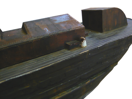
I wanted a flush riveted iron hull with
straight stem and fantail stern and three islands. Glenthorne Rose is an
amalgam of the typical features of this type of vessel built at the end of
the nineteenth century. I wanted the plates to be bashed and buckled after
a very hard life, and one hold being opened, showing how this is done. The
computer generated drawing below shows just what I wish to achieve.
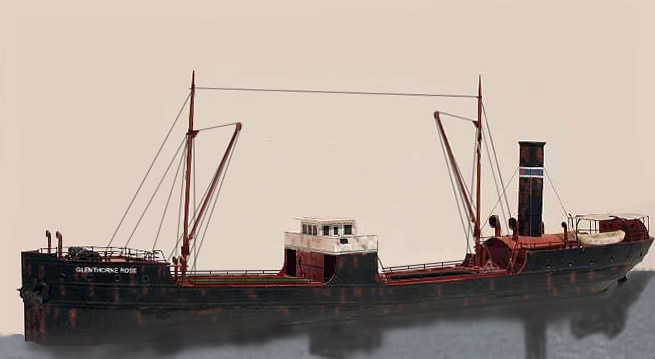
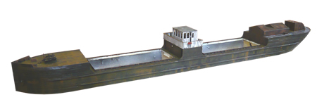
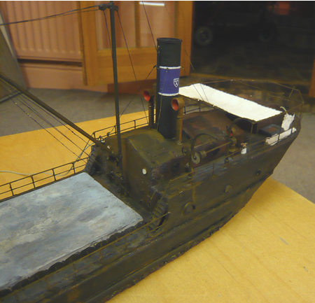
rust bucket 'Glenthorne Rose'
(original computer drawing)
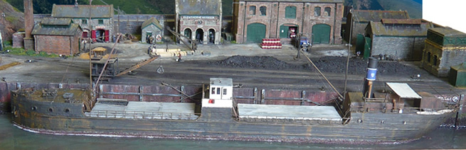
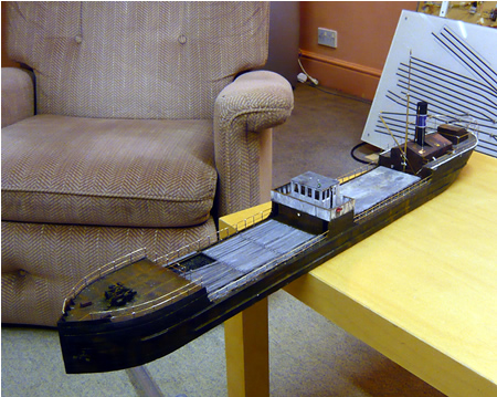
the completed model
I checked beam to waterline length to be typical of
the period and mugged up a bit on ship building techniques of the period.
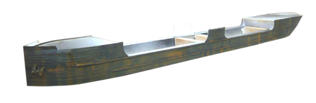
The shape of the hull was first cut out of 4mm ply
and the second layer also cut. Once satisfied with the shape, in particular the
start of the fantail, the bottom layer was prepared for fastening to the
baseboard. The ply edges were covered in epoxy resin and once cured, very thin
Plasticard sheet was cut into plates and fastened to the hull using plastic
weld. a more generous application of plastic weld results in the plates settling
down nicely onto their overlaps. Remember to start plating at the stern and work
forward.
The plates were then primed and sprayed black and
rust worked into the plate joints. They were then 'treated for seaweed' in the
same manner as the harbour walls, (little on the bows though). Once glued into
place, I used self adhesive book binding tape to make the dam at the front of
the harbour water (this
is quite rigid and is easy to fit) and poured in the West epoxy resin. At the
right moment, a gentle swell was worked into water and there we have it! The
baseboard can now be sanded, painted and varnished.
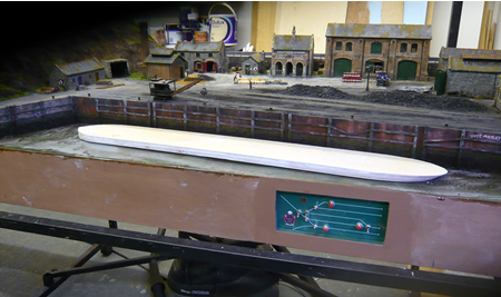
the first two ply layers (a bit warped at this point!) - click on image to
enlarge
The base is now plated and attached to the baseboard and a very mild swell added
in resin - click on image to enlarge
The main part of the hull was made using two wood
lengths for the hull sides and the bow and stern carved in plaster. Carpet tacks
were tapped into the ply at each end to ensure that the plaster adhered.
The hull was then covered in thin Plasticard sheet
cut to the complete hull shape. This was attached using epoxy glue.
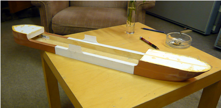
the main hull is complete and ready for
plating - click on image to enlarge
Very thin
Plasticard sheet was cut into plates and fastened to the hull using plastic
weld. a more generous application of plastic weld results in the plates settling
down nicely onto their overlaps. Remember to start plating at the stern and work
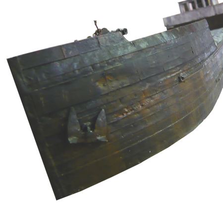
forward. While the plates are still soft they can be distressed to taste.
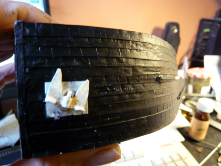
The gouged and battered plating and anchor, (carved in plastic)
- click on image to enlarge
hull painted
- click on image to enlarge
click on image to enlarge
A lot of trouble was taken to get the hull
well and truly bashed.
click on image to enlarge
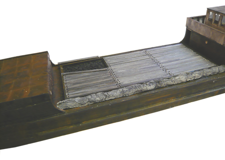
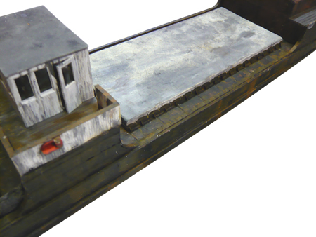
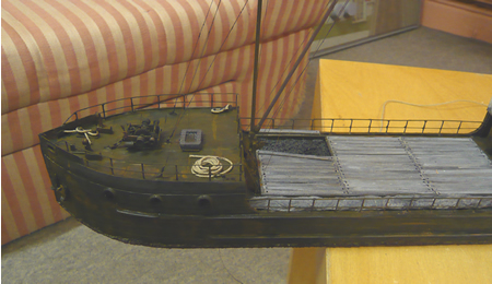
I have never seen a model of a freighter
where the hold tarps are being opened up, so this was my chance. The rear
hold is still fastened down and the front has had the tarp rolled off and
the boards are being removed.
click on image to enlarge
click on image to enlarge
here, someone has started to paint! - click on image to enlarge
The railings are complete and the spars being rigged - click on image to enlarge
Completed ship ready for baseboard. The ship is held in place by 2 screws - click on image to enlarge
click on image to enlarge
click on image to enlarge
|
a few
notes on construction |
The entire superstructure was made using 1/16"
Plasticard. The rivets were punched through very thin Plasticard which was then
epoxied onto the base form. If distressing was required, Plastic Weld was used
instead! The spars were made with brass tube and wire. Everything was soldered
up, including all the railings which were made of wire. The rigging was made
from fuse wire. For best results, the main standing rigging should be brought
through the hull and tensioned from below; this way, adjustments can be made.
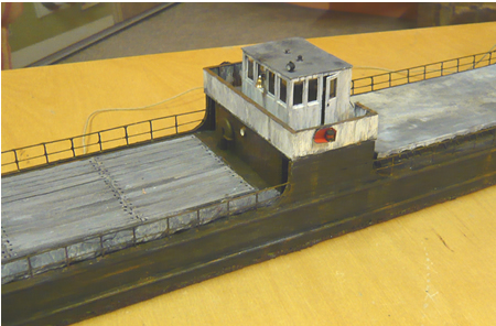
I often notice model boats and ships which are
incorrectly moored.
The diagram above shows the basic principle of
tying up. Because the ship/boat will move with the swell, the lines, after being
attached to cleats, pass through fairleads that prevent damage to the ship and
line. The spring lines are needed to prevent the ship from moving fore and aft
alongside. I notice that these are often omitted.
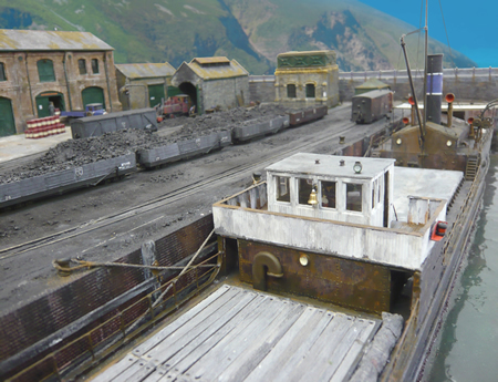
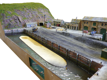
the 'Rose' alongside showing springers

|