|
fitting lights and sound to an L&B train
(or how we got chuffed by DCC Supplies)
Without question, the addition of working
lights to our larger locomotives and railcars have really added to the
excitement of County Gate operations. It is also true to say that the
additional complications of wiring up these locos can take up to an
additional day's work.
On County Gate, loco whistles are operated
from Railroad and Co. and the sound emanates from loudspeakers below the
baseboards. At exhibitions, due to the ambient sound, this does seem to
be a good solution as sufficient volume can be achieved to prevail over
the general 'buzz'. One does have to admit, however, that the effect is
less realistic for home operation.
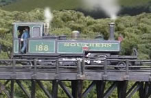
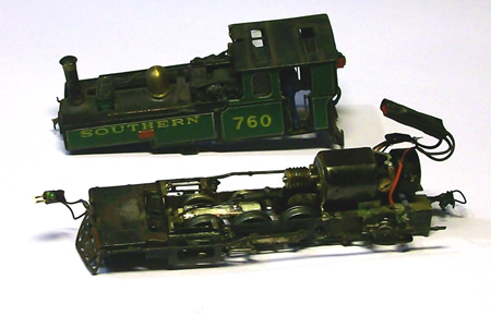
The Lynton and Barnstaple Manning Wardles
are the 'sausage dogs' of the narrow gauge world. I have always loved
them but they are not to everybody's taste. When the railway was
scheduled to be closed, Captain Howey, later of the Romney Hythe and
Dymchurch fame, visited the line with the thought of saving it. He took
one look at the 'ridiculous engines' and walked away!
There are enough issues just to fit the
motor and flywheel into the engine along with a very small DCC chip
(Digitrax DZ125). The cab is compromised but fortunately, the flywheel
is largely hidden by the locomotive crew. The side tanks cannot be used
for electronics as they have to be filled with lead in order to obtain
sufficient adhesion for the locos to haul trains up our grades. If you
are happy without a flywheel, it would be possible to fit the chip and
loudspeaker in the cab. One can order this chip with mobile capability
too although it is twice the price.
As one starts to fit lights to locomotives,
the next issue that raises its head is how to take wires from the
chassis to the body. Early locos fitted by myself used microconnectors
(these can be purchased from Express Models and come up to six prong),
but these do take up a lot of space and the loco cabs get full of
'knitting'.
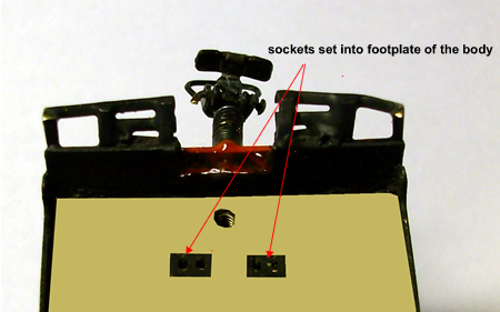
I now build the microconnector plugs and
sockets into the chassis and body. This is a far better solution and
wiring can be minimised and place in the least unsightly locations.
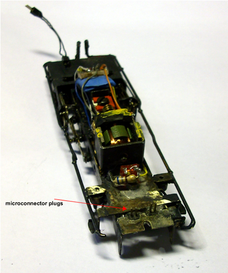
connectors fitted to our latest Manning Wardle - click on image to
enlarge
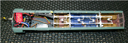
the anatomy of a sausage dog - click on
image to enlarge
Locos are already united with 'companion
cars' in order to enjoy more available wheels, for current collection.
The obvious place to install sound is, of course, the companion car.
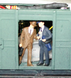
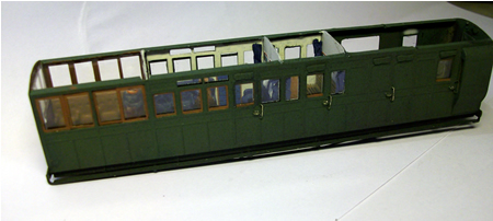
Our trains are designed to operate within
schedules and as a consequence, only one side is ever visible. This has
enabled us to open up the doors in the guards compartment to 'let out
the sound' of the installed speaker. The open apertures were re-enforced
by thin strips.
As the carriages are also going to be lit,
all holes in the floors have been sealed off to prevent light leakage.
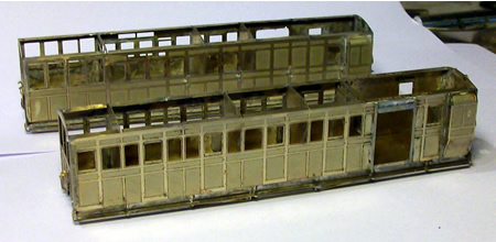 The two new brake cars with guards doors
opened up for sound - click on image to enlarge
The two new brake cars with guards doors
opened up for sound - click on image to enlarge
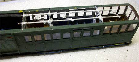
 the first of the coaches nearing
completion - click on image to enlarge
the first of the coaches nearing
completion - click on image to enlarge
Equipment
So let us look at the general wiring
requirement. One pair of wires between stock of this small scale is
about all one can manage as the bending resistance of any more will
derail the stock on curves. As it is, companion cars have to be quite
heavily ballasted to prevent this happening.
The main chip, a Digitrax DZ125 remains in
the loco. This will also operate the loco light, using function 0. The
companion car also picks up track current and this is passed through to
the loco using thin flexible wire supplied by
DCC Supplies
and micro connectors from
Express Models.
To be able to switch on and off the
carriage lights and rear lamp on the coaches, an additional chip is
required. This is a Digitrax TL1 single function chip. This is very low
cost luckily. Power for this is taken from the carriage track power
pickups. The chip is set to the same address as the main chip and
function 0 will be read, thus switching on and off the carriage lights
and rear lamp when required. As delivered, the TL1 needs a little
programming. The loco address has to be set for the required train, and
to switch the lights on and off with function 0, CV 61 has to be set to
1.
The TL1 needs to be removable for
programming as the sound chip and the TL1 have some programming
incompatibility. I used Express Models micro connectors to do this.
Fitting instructions for the TL1 can be
found here
 wiring schematic - click on image to
enlarge
wiring schematic - click on image to
enlarge
loco
and carriage lamps
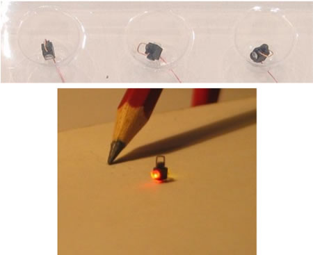
DCC Concepts in OZ produce tiny working
loco lamps. In the UK, they are supplied by
DCC Supplies
but at over £31 for six, they are definitely not cheap. We have found
the red lights seem to be effective but so far have problems with the
white lights. These are not warm white, as one would expect from an oil
lamp, but are that horrid blue white light which is, in my mind worse
than no light at all. The manufacturer suggests that the problem could
be solved by painting a tinted varnish over the optic.
The lamps are actually too small to Lynton
and Barnstaple in 4mm/ft.
The wires of these lamps are very fine
indeed and require careful handling. They are in fact so fine, that in
many cases, they need not be hidden.
A separate circuit is used to power the
rear carriage lamp in order to be able to correctly adjust the intensity
of the light A resistor up to 10Kohm may be required..
carriage lighting
The carriage lighting uses warm white
sub-miniature lighthouse LEDs, again from
DCC Supplies.
These are soldered to a couple of brass wire bus bars which are glued
onto the top of the coach cross partitions. Short lengths of heat shrink
sleeves are used to insulate the brass bus bars from the metal
partitions. It is important to use the correct resistors to ensure that
the carriage light intensity is correct. I have found that 6 to 9Kohm
resistors are ideal for us. If one coach has less LEDs than another, it
is necessary to add an additional resistor so that the coach lighting
intensity is equal. Our coach lighting is actually quite dim as indeed
it would have been.
 coach fitted with lighting - click on
image to enlarge
coach fitted with lighting - click on
image to enlarge
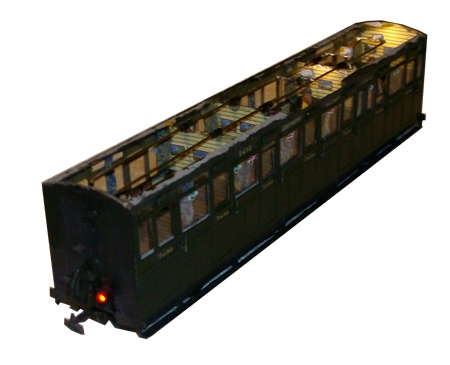 only some of the coach lighting is
installed at this point
only some of the coach lighting is
installed at this point
Of course, when wiring the connection from
one coach to the next, it is important that the polarity is correct for
the LEDs to operate.
DCC
Supplies
Once the donkey work had been completed, it
was time to trolley off to
DCC Supplies;
fortunately very close by to us, just outside Worcester. The company
resides in what must be one of the most pleasant business parks north of
Watford. Nestling amid pine trees, meadows, a recreational lake and a small
caravan park, husband and wife team Andy and Fiona have recently moved
into a most spacious and well presented premises. The company is quickly
enlarging its stock of model makers materials and is well worth a visit.
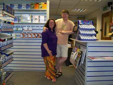 Andy and Fiona DCC!
Fiona tramples over all the usual
stereotypes
of females and models railways... she actually knows a lot about them
and is herself an expert on DCC operation. While Andy got to work
fitting the function chip, Fiona programmed the sound chip.
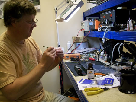
working on 009 stock is like being a keyhole surgeon - click on image to
enlarge
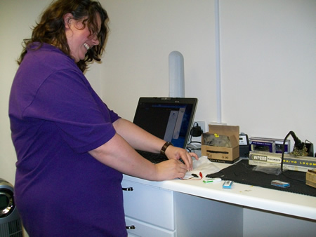 Fiona finally persuaded the sound chip
to be a steam engine rather than a diesel!
- click on image to enlarge
Fiona finally persuaded the sound chip
to be a steam engine rather than a diesel!
- click on image to enlarge
It was not long before everything was
neatly installed in the baggage car. I am amazed at how small the loud
speaker actually is. It belts out a fair bit of volume too! Andy also
installed a capacitor between the two lighting wires which stops
flickering lights on bad bits of track.
 the completed installation
- click on image to enlarge
the completed installation
- click on image to enlarge
There was even enough room to carry a few
Albanian refugees too!
After very little hassle, the train was
chuffing along the test track... see the
video here.
There is still some programming to do. This
includes assigning the required sounds to the specified function
numbers. One will be a guards whistle which can be added to the chip.
The chuffs also need to be adjusted so that there is the correct 4 fours
per wheel revolution. The sound of draincocks can be added for
starting and the occasional safety valve blow off when stopped.
Programming of the chip, and even the loading of your custom sounds is
actually done through contact with the rails.
On returning home, the train was quickly
railed onto County Gate where it happily chuffed around. Our neighbours
arrived quite quickly to watch and the general consensus was that the
effect is a rip roaring success. Hopefully, it will be possible to
easily adjust the sound volume where required as this would greatly
increase realism on a larger layout.
We started out with the wish to add sound
for our new Bratton Fleming layout but now also hope to treat County
Gate to the technology.
Following a second visit by Fiona of DCC
Supplies both trains have now been programmed to work correctly. Our own
choice of whistle sounds were loaded into the chip but for some reason,
we were unable to add a guards whistle. We tried several sound samples
but they just sounded like Casper the Ghost!
The number of chuffs per revolution was
adjusted as indeed was the volume.
To programme this chip, a fancy circuit
board is needed along with a good understanding of computers. There are
three volume levels for the main sound, (the chuff). In addition, other
sounds can be added to the chuff, such as braking, draincocks and pumps.
Additional sounds are actuated by function
switches and these seem to have to be pushed twice to actuate the sound.
There is no volume control for the function switch sounds so this has to
be adjusted before loading into the chip. The sounds have to be in mono.
Audacity is the perfect programme to do all of this.
It can take quite a few minutes to load the
sound to the chip and then the result has to be tested. It took the best
part of a day before we were happy with the results.
It appears to be difficult to assign
function numbers to a particular sound and we have not quite managed to
do this yet.
The result is convincing and excellent. It
is important to maintain the sound levels correct for viewing distance
and scale. Only too often, I see the sounds being played far too loud.

|