'Work began
on the funicular in early 1929. The car bodies were not
initially fitted as the funicular was used to carry all of
the building materials for the construction of the lido,
below. Although initially water powered, it was soon
discovered that the balance would be lost when passengers
left or joined the cars at the half way station. As a
consequence, electric traction was installed, the powerful
winding mechanisms being imported from Switzerland.'
Construction
of the model was based on the Langley funicular kit. We did
not purchase the control unit as ours also had to stop midway.
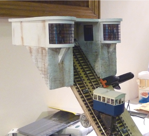
The Langley model is designed to follow a slope of 45
degrees. It was not possible to incorporate a track of that
angle on Cliffhanger and our trackbed is actually 52
degrees. This necessitated a complete rebuild of the kit,
the chassis being taken apart and rejigged. I also built the
cars with curved ends which I felt was more compatible with
our art deco theme. I found the Langley instructions as
clear as mud, by the way.
I fitted
slatted seating to the cars; also from Langley. The water
tanks are filled with lead shot.
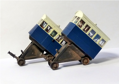
The completed cars -
click on image to enlarge
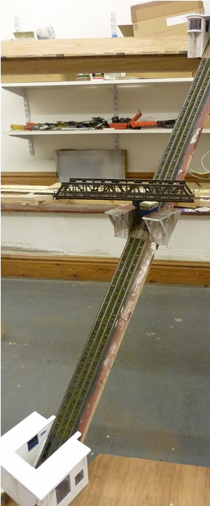
The 00 gauge
track was laid onto the funicular trackbed using a spacer to
ensure the correct distance between them. The whole arrangement was then set up at my
workshop at the correct angle and work was begun on building
the platforms and buildings.
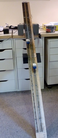
click on image to enlarge
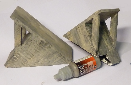
As the
funicular was built in 1929, I assumed that concrete would
have been the main construction material.
click on image to enlarge
Once the six
platforms were built in foamboard, they were coated in PVA.
A very thin coat of premix Polyfilla was then rendered over
them and a metal strip drawn across to leave marks depicting
shutter boards. The platforms are left removable at this
time for detailing and painting.
Finishing
was with acrylic washes and while the paint was still a
little damp, Eazi weathering powder was applied. This is by
far the best powder I have come across so far.
The top station was built in
foam board. The Crittall windows were printed on self
adhesive clear vinyl and stuck to transparent acrylic sheet.
A large 'CLIFF RAILWAY' sign is to be added to the roof. The
supports for the building are made of shuttered concrete
while the building itself is rendered concrete. Weathering
would have been quite rapid in these maritime conditions.
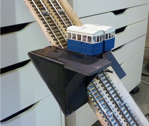
The funicular trackbed was then
offered up again to the baseboard and the top and middle
stations attached, ensuring that they were plumb. It then
became obvious that despite all our planning, the railway
bridge had been built 4" too far to the right. This was not a
hard job to put right luckily.
In the photo below, the track
and rollers have been painted.
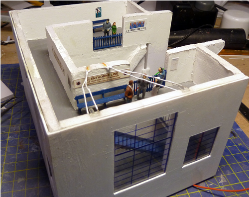
The lower station under
construction. click on image to enlarge
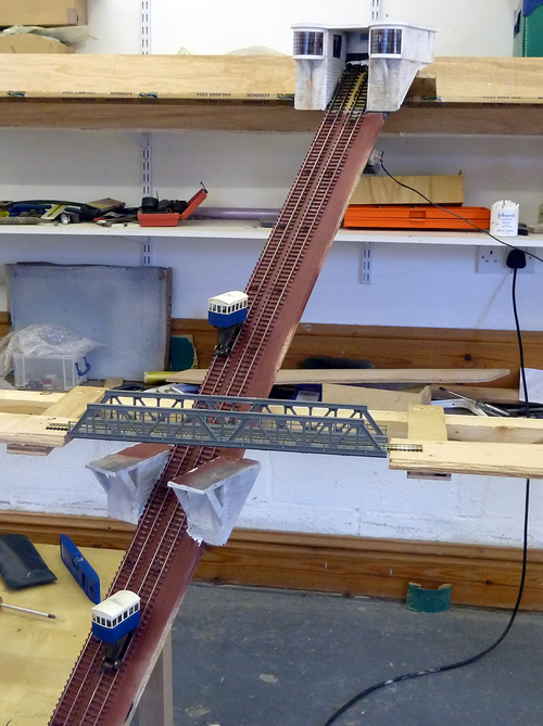
The next step was to convert
the track to baulkway which is typical of funiculars. In the
photo below, the bridge is in its correct place and the
weeds between the baulkway can be seen.
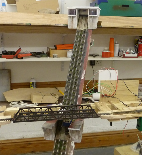
The photo below shows the lower
station roughly in place. The roof over the tracks is not
yet built.
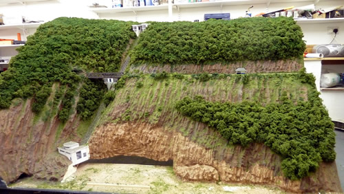
The
funicular is incorporated into the scenery
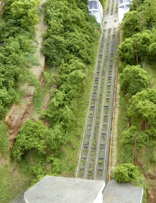
The fully
detailed track
The operation of the funicular
appeared to be simple indeed. Reed switches set into the
track would be operated by magnets fastened under the cars
and the whole would be controlled by a simple off-the-shelf
shuttle system. That is when the troubles began!
1. Fishing line was recommended
as cable. We discovered that all fishing line stretches and
the positioning of the cars was constantly changing. A move
to beading thread cured this particular problem.
2. We then discovered that reed
switches were not totally reliable. On occasion, the magnet
was not detected which resulted in a car being driven
against the back wall of the upper winding house. The cable
would break and the car crash to the bottom with the loss of
all hands!
3. We initially used the motor
supplied by Langley. This drove both cars from pulleys
attached to a common shaft. The motor was geared and was
difficult to control.
4. We found that the cable
would build up on one side of the pulley and then drop down
to the bottom of the V. This resulted in the car violently
dropping and then derailing.
It quickly became obvious that
no amount of tweaking would improve the situation. Very
fortunately, Andy and Fiona Forty of DCC Supplies came to my
rescue. Two step motors were fitted. These motors count 200
positions per revolution. One revolution equals 1mm of
movement of the car. Electronics accurately count the
'clicks' so that the cars are always perfectly positioned.
The electronic hardware developed by Andy was programmed
using his laptop and we haven't looked back since.
My contribution was to solve
how to evenly lay the cable onto the pulleys. It was too
simple for words: build in pulley wobble!
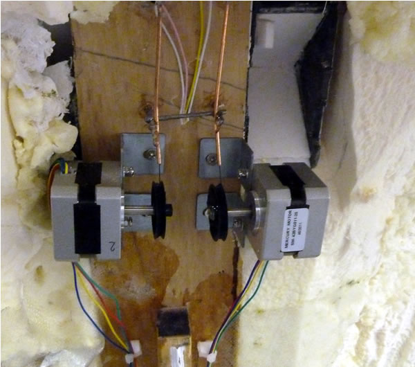
The stepper motors. Positioning
of the copper lead tubes is critical.
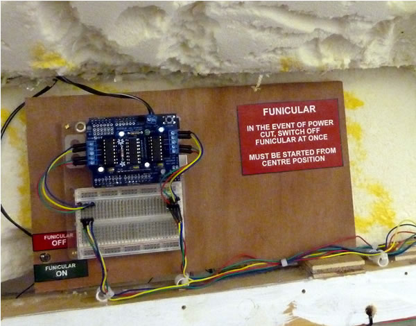
The one off electronic
control board developed by DCC Supplies.
It is essential that the
funicular is always started with the cars accurately
positioned at the mid way station. If it is started in any
other position, disaster will result. For this reason, we
have an uninterruptible power supply (UPS). In the event of
a short break in power supply, the funicular will continue
for a while and the UPS bleeps loudly. This gives us the
opportunity to stop the cycle with the cars in the correct
position.