|
wiring diagrams
There were complications in the wiring as we
wished to retain manual control of the track as well as using Loconet.
After over 30 exhibitions, we have never needed to return to manual
control and in October 2011, this wiring and panel was removed as there
was too much complication.
In 2012, the trackplan of the station was
revised. Manual override has been reinstated for points 19 and 15
(station throat), and for points 16 and 17 which operate in tandem.
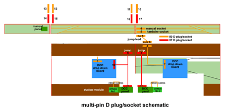
Switchover is by a simple multi-pin plug arrangement at the rear.
The 'Shuffle was also removed as we found
that too much time was spent changing the programming should we wish to
operate another train.
All wiring diagrams shown are after the
modification.

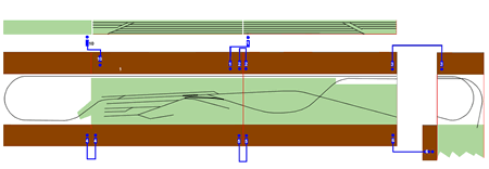
connection schematic - click on image to enlarge

harbour schematic - click on image to
enlarge

multi-pin schematic - click image to
enlarge

DIN schematic - click image to enlarge

|