|
Rolling stock
Vorsprung durch Technik and Manning Wardles
I am often asked why I keep trying to find an
easy way to fit an RTR chassis under Backwoods Manning Wardles. The
answer is simple. I feel I am a reasonable modeller but I am not a
miniature model engineer. Despite three attempts to build a viable
Backwoods chassis for these locos, I have failed every time.
Equally, if anything subsequently happens to
a Backwoods chassis, one almost has to build a new one.
I have had to rely on outside experts. This means costs of at least
£250 a pop and usually a long wait. Having seen the lovely Leek and
Manifold models of Martin Radcliffe
which are based on the Bemo outside frame chassis, I set out to find one. They run as
smoothly as can be.
My attempt to use a Grafar class 08 chassis
has resulted in a successful locomotive which still runs well but the
effort was considerable.
The Bemo chassis layout fits under the MW
body although, yet again, the motor will require moving as it is 1.5mm
too high but the job is considerably easier. It is also much more narrow than the Grafar chassis. With the
plastic side frames cut back and thinned, the Backwoods chassis frame
fits nicely over it. As with the Grafar 08 chassis, the wheelbase is
less than prototype but I feel that this really does not show.
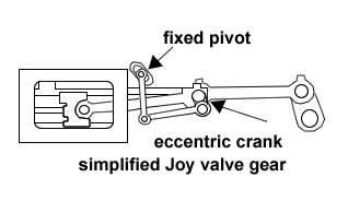
I am also going to use a simplified
Joy valve gear, as this is another extremely difficult thing to get
working. Bob Barnard, who has modelled these locos over the past thirty
years, uses a simplified system himself and I have to say, the
appearance is just as good.
The additional Manning Wardle is being built
for the Marches Narrow Gauge Group who will be the operator of the
Bratton Fleming diorama currently under construction.
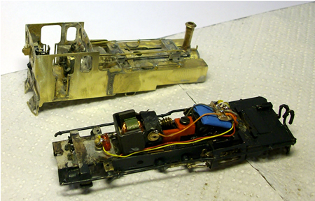
I was lucky enough to recently find and
outside frame Bemo diesel on Ebay. Not cheap at £142 but still much cheaper
than from a shop.
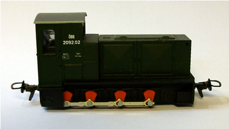
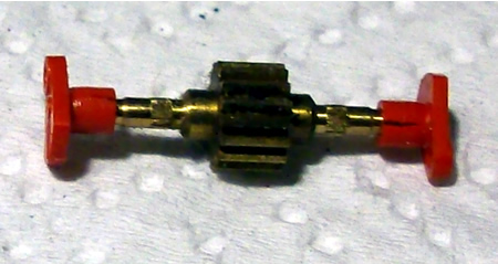
as delivered
as delivered - the jackshaft despite
having a gear, is not driven
Round here, nothing remains unmodified for
long, so the body was removed, the jackshaft removed and the coupling rods cut
short. The footplate was cut away and the outside frame refastened with
epoxy. The outside frame holds the electrical pickups, so it is best to
leave them where they are. Looking at the build quality, I have to say
it is miles better than anything else around.
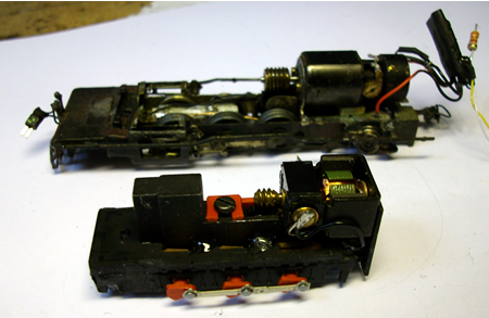
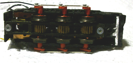
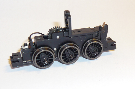
the basic modified chassis alongside a
Backwoods Manning Wardle chassis. The wheelbase is shorter than an MW
but frankly one can barely see the wheels anyway! - click on image to enlarge
As the strip down continued, I noticed that
there was a split in all of the cranks. This is not in itself a disaster
but measures have to be taken.
click on image to enlarge
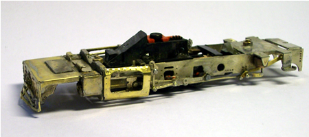
The cast adhesion weight had to be cut down
to clear inside of the loco. The underside of the chassis was sanded
down at the front end to allow for the installation of a pony truck. In
the photo below, the split cranks can be clearly seen.
The counter balance
weights on the cranks were also removed with fine snips and a sharp
knife. The crank pins are in plastic and the pins of the driving wheels
are pinched at the rear to hold them in.
click on image to enlarge
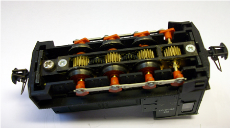
The wheels sets and spur
gears were then removed and the plastic side frames removed.
A Backwoods 'Russell' frame which is the
same width as an MW frame. This is a good time to paint the wheels and
cranks - click on image to enlarge
There is really not that
much left of this expensive chassis. So what do we get for the
investment?
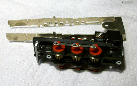
1. Current collection.
This is well made and fits on the underside of the plastic footplate
unit. The phosphor bronze pickups act onto the wheels rims; the ideal
position.
2. The axles are made in
brass and are of 'agricultural' thickness. These slot into the inside
frame which is very accurately machined. There is not one iota of
sideplay. Brass is a far better material to rotate in the chassis slots.
3. The gears are also
agricultural and all wheels are driven by spur gears. This means that
the coupling rod is more or less cosmetic. The hole at the rear
axles is round while the other two are slotted, which compensates for
any gear slack.
4. The keeper plate is a
very well engineered part in metal, for a change and fits perfectly,
preventing and extraneous movement of the axles.
5. All wheels make
contact with the rail (not always the case with Grafar) and all wheels
turn absolutely round without any trace whatsoever of wobble (another
Grafar problem).
6. The cranks are sturdy
but have all cracked with time (my unit was bought second hand but had
not been tampered with or barely run). This is fixable with the use of
Loctite but the problem should never have happened in the first place.
The cranks fit onto splines, so on dismantling, good quartering is
necessary. The Grafar cranks fit into holes, so they self quarter.
However, Grafar wheels are very prone to come loose on the axles.
The chassis with wheels removed. Note
how I have relieved the rear of the chassis to accommodate the pony
truck
- click on image to enlarge
The hole where the jack
shaft was installed is filled with a thick piece of Plasticard which is
glued in place. A retaining nut is let into the plastic for the pony
truck fixing.
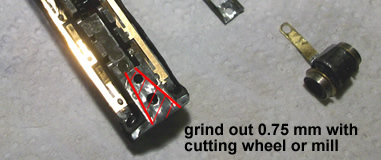
The only place to attach
the front pony truck is using the screw that holds down the keeper
plate. It is necessary to grind away to half thickness some of the metal
around the hole to allow for the thickness of the pony truck arm which
must have free movement side to side. Be careful to leave the shoulders
intact to enable the keeper plate to still function correctly. Likewise,
with the wheels and spur gears removed, the chassis must also be
relieved to give movement to the pony truck arm.
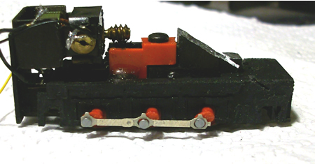
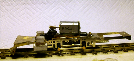
The motor is held in
position with 2 screws. This was removed and the backplate cut off. The
motor was then re-attached as shown in the photo below. I used epoxy
glue to fix it. Care is needed to ensure that the gears mesh correctly.
In this position, all is well clear of the body except that the top of
the motor, (a plastic block) needs to be sanded down a bit. I have
marked this with a red line.
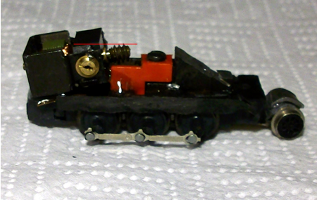
the repositioned motor - click on image to enlarge
Obviously, first time
around, quite a bit of time was wasted just figuring it out and faffing
around. The chassis is now ready for installation into the Backwoods kit
and conversion takes around two hours of easy work. Time was lost
rectifying the cracked cranks. The chassis runs extremely smoothly with
no wobble at all and is actually very powerful indeed.
The
Joys of valve gear
Joy valve gear is not
very usual (except with the LNWR) and I rather suspect that even the
Festiniog Railway, who are building a replica 'Lew' are a little scared
of it. Walschaerts valve gear is excellent for a model as there are lots
of bits flying around which is visually very stimulating. Joy valve gear
is a much more demure affair and in reality there is very little motion.
Because the gear tends to be over scale in 009, the amount of visible
movement is much greater than in prototype.
Below is a photo of the
full Joy gear as built up from a Backwoods kit. The problem is the tiny
link between the connecting rod and eccentric rod. Apart from being
extremely difficult to put together in the first place, experience has
shown that this is where a failure is most likely to take place. The
eccentric rod will then drop down to the bottom of the expansion link
and virtually scrape on the ground, where it is further damaged until
the whole lot fails. What is so annoying is that it is virtually
invisible anyway!
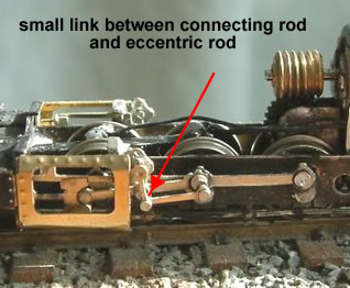
overscale Backwoods valve gear
The simplified Joy gear
dispenses with the 'link from hell' which is instead used as the
eccentric crank. This will minimise the movement of the valve gear which
will make it more accurate. The 'link from hell' could actually be solid
soldered onto the connecting rod so the it looks as though it
works!
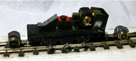
The completed and tested chassis waits
now for the delivery of the Backwoods kit
There was a small delay in receiving the
Backwoods kit as Pete had run out of etchings.
The first job was to fill the main bearing
holes and slots above them in the chassis for both outer drivers. New
slots were then cut to clear the cranks of the new chassis. The chassis
was then folded and the cylinders made up and fitted along with the
front buffer beam assembly.
It is now the time to carefully offer up
the Bemo chassis. We had to remove more from the front of the chassis
but quite quickly it slip in just fine. Two fixing points were
established, front and back so that the chassis is firmly held in the
correct position and height.
The cranks were then removed, one side at a
time. They were shortened and the axle holes drilled right through. They
were then refitted leaving 0.5mm clearance between the outside of the
frames and the back of the cranks. They were attached using Loctite 603
and the coupling rod also refitted, with the front and back crank pins
fitted with Loctite.
The simplified Joy gear went together very
easily. New centre driver crank pins were fabricated from brass and
soldered to a return crank (there are many supplied in the kit). The
brake rodding and remaining detail followed quickly and easily. Time
taken to reach this stage was 14 hours. The motor was removed at this
point and the chassis thoroughly cleaned.
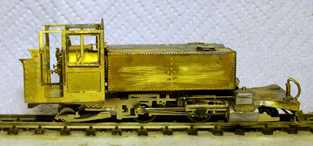
the chassis is nearly complete - click on image to enlarge
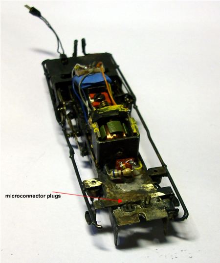
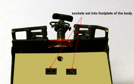
The body went together with little changes.
There is now room to include full cab detail, including the firebox. In
order to minimise wiring, micro-connector plugs and sockets pass wires
from the chassis to body.
the chassis is nearly complete - click on image to enlarge
chip installed which is wired up for rear light operation andred light in firebox
reflecting onto the track
- click on image to enlarge
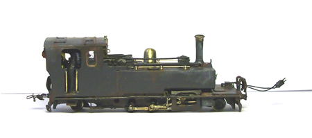
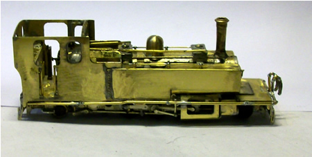
The loco sprayed and weathered awaiting panelling and lining.
- click on image to enlarge
the
verdict
The Bemo chassis is very well engineered
although there were concerns that in our example, the cranks showed some
cracking. The driven wheelbase is shorter than the correct Backwoods
chassis and I was concerned that we would experience problems. This has
not been the case although more careful balancing was needed when adding
weight. We have previously added lead shot as weight. In this example,
it was important to keep the ballast over the driven wheels and we have
used 'Liquid lead' which is much more compact and therefore more
weighty.
We did experience some meshing problems
between the wheel drive train and the spur gears to the motor worm
drive. These are held in a red plastic moulding which is clearly visible
in the above photo. Careful paring with a Kraft knife allowed for good
meshing.
The smaller wheels do mean that there are
more 'chuffs' per mile but this really does not matter as our sound unit
can easily be adjusted to suit.
The loco runs as smoothly as
the best we have on County Gate although I suspect that it is a little
less powerful as it is more prone to wheel slip. It does, however easily
haul typical L&B consists with ease, even up the CG grades. On the
Bratton Fleming layout, where it is destined to work, there are
no problems at all as the layout is quite flat.
All in all, a very successful build and far
easier to achieve than struggling with the standard Backwoods chassis.
Future maintenance will also be a breeze.
2-4-2 Baldwin
Lyn
The chassis of
my original 'Lyn' was built by Peter
Wallace, who reported that it was extremely
difficult to get right. The design is
supposed to have compensated suspension.
Sadly this did not work well and the system
was locked. The loco is still running very
well although the axle boxes are a bit worn
now.
For the new 'Lyn' to be used on our Bratton
Fleming layout, I was determined to use a
mechanism which allowed for easy maintenance
and had thought of using the new Lilliput
chassis which is due out soon. In the end, I
elected to maintain the correct wheelbase as
it would have been very difficult to do
otherwise with the etched bar frames. I
therefore decided to turn a Grafar class 08
chassis into the motive power.
I always try to
build my models without the help of lathes
and other fancy tools, which most modellers
only dream about. This project was no
exception.
The Grafar chassis was reduced to the metal
block and gearbox and the rear was cut away
to accommodate a new axle position. This was
obtained by cutting it out from a scrapped
Grafar chassis (an early Mallet attempt
which was superseded). The additional block
was epoxied in place to render the correct
wheelbase. By laying on a glass plate, it
was easy to get things all lined up
correctly.
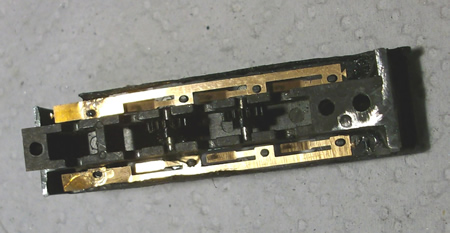
The Grafar
keeper plate was modified, the phosphor
bronze pickups being removed at this time.
In order to
give strength to the plate and also for the
gears to clear, two small square section
brass rods were glued to the plate.

The phosphor
bronze pickups were modified and glued to
the sides of the chassis block ensuring that
two of the pickup arms rubbed in the correct
position and that the epoxy glue joint
insulated from the block. The plastic
carrier as was removed from the motor as
this is too high to fit in the loco. The
motor is easily just glued to the block
instead, ensuring correct gear meshing.
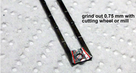
The cranks were shortened using a craft
knife and once set, fitted and set onto the
axle extensions using Loctite 603. The axle
extensions need to be shortened by about
.75mm so they are flush with the cranks. Fit
the Backwoods coupling rods which need
opening out just a little to fit the crank
boss and thin the end just a little on the
rear driver. The Grafar crank pins can be
fitted and the quartering adjusted until
perfect. The Locktite takes 24 hours to set
to there is plenty of time to get things
right.
The Backwoods chassis can then be assembled
with the driver holes cut into slots. The
Grafar chassis is attached using two screws
with captive nuts. The ride height was easy
to adjust with thin washers.
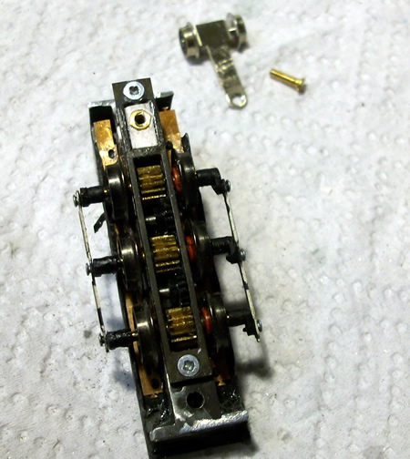
the Grafar
chassis is offered up to the modified
Backwoods frame for the first time - click
on image to enlarge
The connecting
rods and cross head from a Roco chassis was
used rather than the Backwoods offering as
the plastic crosshead wears less than the
brass casting. The Roco connecting rod is
also a lot thinner and allows the original
Grafar crank pins to be used.
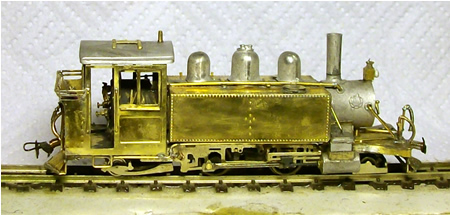
the body
begins to take shape over the completed
chassis - click on image to enlarge
The model is
fitted with a Digitrax 125 chip and has
front light, and red glow from the fire door
and down onto the track from the grate. Note
the two plug/sockets at the rear of the
chassis/body to transmit power to the lights
and to bring in track power from the
companion car.
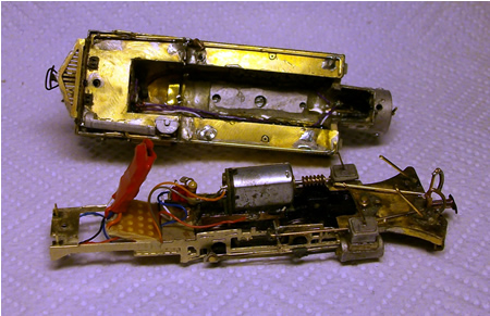
the anatomy
of Lyn - click on image to enlarge
More or less
complete and now awaiting paint - click on
image to enlarge
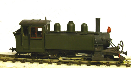
complete bar lining and transfers - click on
image to enlarge
carriages
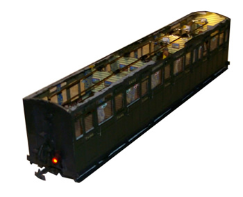
Only four
coaches are needed for the diorama. They
have to be built new as interior detail is
very important due to night operation with
carriage lighting and they are, of course treated with snow. We have used
3dPerfect kits which are actually only
available now on special order. Each train
has have a brake coach and one other. Langley
coaches are still available. You can see how
to build an etched coach
here
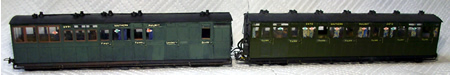
the first
completed train fitted with sound and lights
- click on image to enlarge
Do not fix
the roofs on the coaches until you have read
'light and sound'.


|
